 | Seismic-reflection profiling |
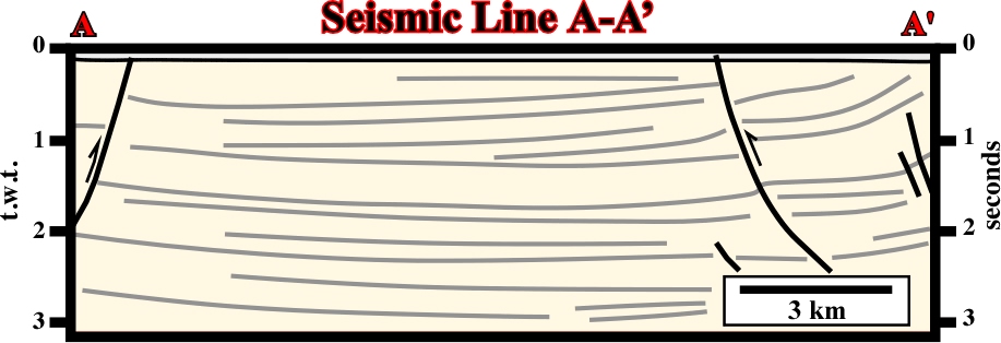
This seismic profile (N-S) is representative of the area where it was shot. It is perpendicular to the structural trend. Therefore, one can say that sediments were shortened and uplifted. So, the maximum effective stress, 1, was horizontal and striking N-S. In other words, in the area, the predominant structures are (i) cylindrical folds, (ii) folds associated with tectonic inversions and (ii) thrust or reverse faults. It is relevant to point out that in a reverse fault the shortened faulted block is almost always the up-thrown block, as illustrated (reverse fault around 2 seconds, in the left part of the line). On the other hand, taking into account the different thickness of the faulted blocks (upthrown block is thicker) it is not reluctant to hypothesize the large anticline structure is associated with a tectonic inversion of a pre-existent normal fault. |
On the above geological cross-section it is relatively difficult to corroborate the volume problems in depth. On the contrary, it clearly indicates the sediments were shortened and uplift. Subsequently, one can say that the tectonic regimes responsible of the shortening was charcterized by a 1 horizintal and a 3, and the more likely structures are cylindrical folds, reverse faults and thrusts. Such a knowledge, strongly help the interpreation of the seismic line (roughly parallel to the cross-section). Indeed, in depth, the sediments accommodated to the volume problems mainly by reverse faults, which are difficult to recognize on the upper levels and in surface |
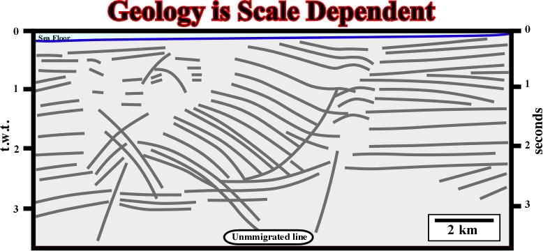
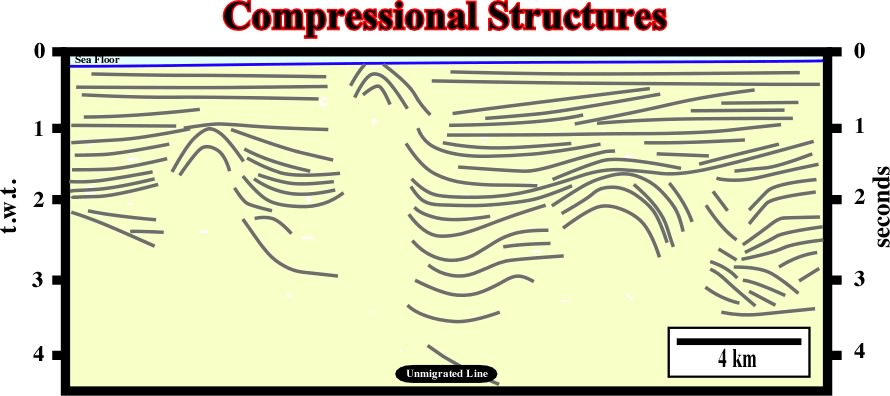
Seismic lines are roughly time profiles. So, when interpreted, in geological terms, interpreters should not forget that Geology is scale dependent. In other words, interpreters must take into account not only the horizontal and vertical scales but lateral velocity changes as well. In addition, when working with unmigrated seismic data, as seismic horizons (chronostratigraphic lines) are not in its real position, the geometry and internal configuration of seismic interval must be carefully determined. |
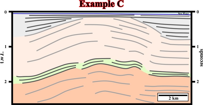
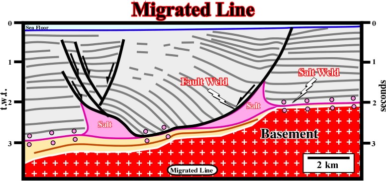
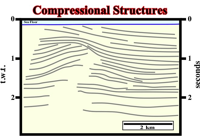
The migrated version of the previous line, in spite of the fact that vertical scale is in time, has the appearance of a cross-section. The large majority of the diffractions has disappear. However, the seismic reflections are not in their really position and the lateral changes of velocity is not apparent. Therefore, the interval thicknesses and the dip are the reflections is apparen |
When migrated seismic lines were not available, this method was quite usefull. Presently, as the large majority of the seismic lines are migrated, it becames obselet. |
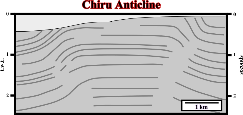
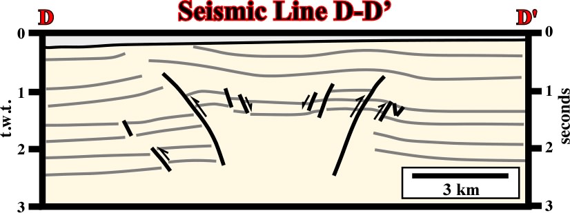
On this seismic line, it is quite evident the sediments were shortened, and so uplifted by a compressional tectonic regime with s1 roughly parallel to the trace of the profile. The folding (concentric) was not sufficient enough to accommodate the sediments since reverse faults on the flanks of the anticline are easily recognized particularly on the right flank. On the contrary, the small strike slip faults allowing the lengthening of the anticline along the 2, recognize on the geological maps, seem to be under seismic resolution |
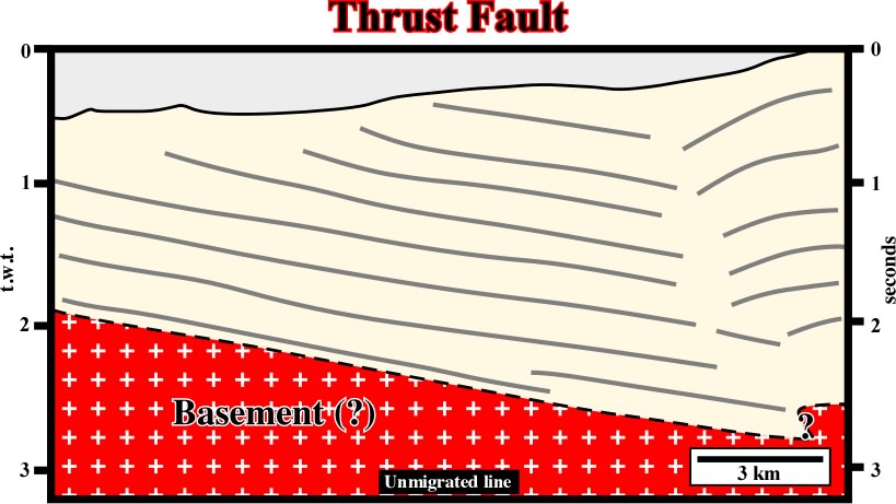
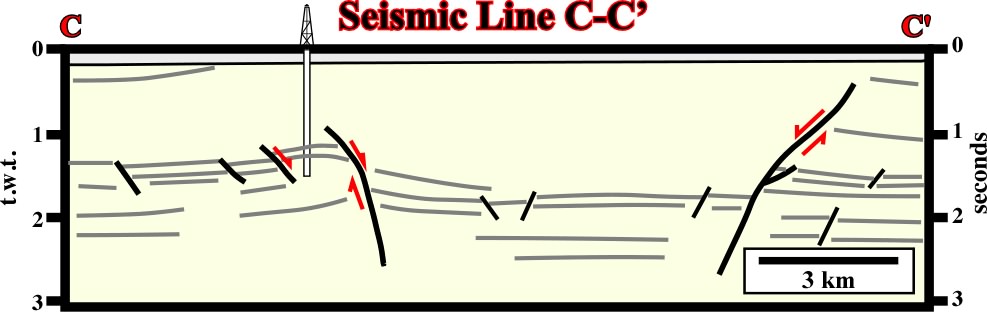
On this line, the uplift of the sediments underlies a shortening created by a compressional tectonic regime with a 3 vertical. The shortening was made by folding (cylindrical folding) but also by reverse faulting. Indeed, on the right part of the line (around 1.8 s depth), a reverse fault, affecting a relatively high amplitude reflector, is easily recognized. A close look to the thickness of the seismic intervals allows to associated the reverse faulting to a major tectonic inversion. In other words, it is likely that the reverse faults corresponds to a reactivated pre-existent normal fault. Indeed, the thickness of the sedimentary intervals forming the hangingwall (upthrown faulted block) is higher than that of the footwall intervals |
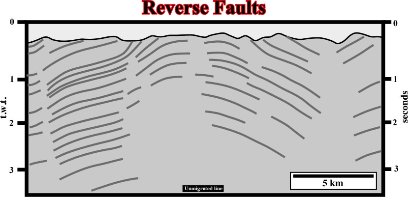
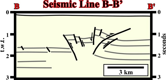
On this seismic line, roughly paralle the 1, the sediments were shortened and uplifted. Several faulted blocks are easily recognized. Some of them are upthrown blocks and other downthrown blocks. A seismic interpreter knowing the basic principles of Tectonics takes the fault planes as reverse (only reverse faults can shorten the sediments). On the other hand, as suggested in the previous figure, the shortening is mainly realized on the upthrown faulted, so, the fault planes must dip toward the upthrown blocks, as it is the case in all reverse faults. On this subjects, it is quite important to understand that in the majority of the seismic lines there are no reflectors associated with fault planes. Actual, as depictecd on this line, a fault plane is just a mental construction underlying the discontinuity between the reflectors (chronostratigraphic lines) of the faulted blocks |
On this line, one can find the geological principle allowing identification of reverse faults: (i) the faulted blocks (downthrown and upthrown) are easily recognized by the associated seismic surfaces, (ii) the shortening is located in the upthrown block, (iii) the fault planes dips toward the upthrown block, (iv) the downthrown blocks are slightly tilted with minimum of shortening, (v) the topography of the ground corroborates the reverse faulting interpretation, i.e. the maximum shortening is the upthrown block: shortening induces uplift |
On this seismic line the shortening is not quite quite evident, since the geometry of the faults seems normal, i.e. the inversions is relatively small |
On this seismic line the shortening is evident. All faults have a reverse geometry, i.e. inversion and reactivation was strongly enough to change the fault geometry. |
In spite of the fact thyat locally shortening is evident, one can say that on this line extension is preponderant |
Here again, inversion was strong enough and so the geometry of faults is predominantly reversal |
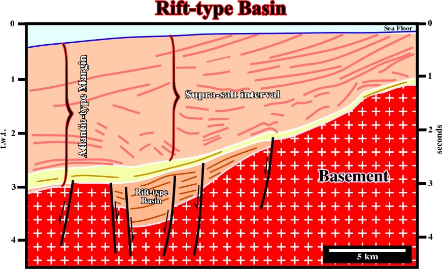
A rift-type basin is clearly recognized within the basement and below the sediments of the the overlying divergent margin, in which a salt induced tectonic disharmony allows to differentiate supra and infrasalt sediments |
Several compressional salt structures (anticlines, reverse faults), detached from the basement can be recognized on this seismic line from south onshore France |
On this seismic line from the Tanganyika Lake, one cannot say if it corresponds to a transfer basin or to a normal graben. Such a differentiation requires to known how the faults strike in relation to 2. |
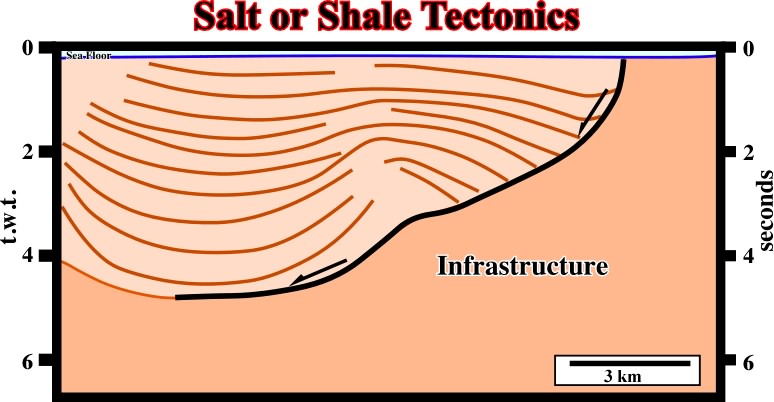
A major tectonically enhanced unconformity separates two tectonic realms. The older one was compressional. The salt layer and its cover were strongly shortened and uplifted creating a major erosional surface, which underlies a significant stratigraphic cycle boundary. In this particular line, it is difficult to see is the basement is or not involved on deformation. Notice that on seismic lines the bottom of the salt layer usually shows a velocity anomaly (pull-up). |
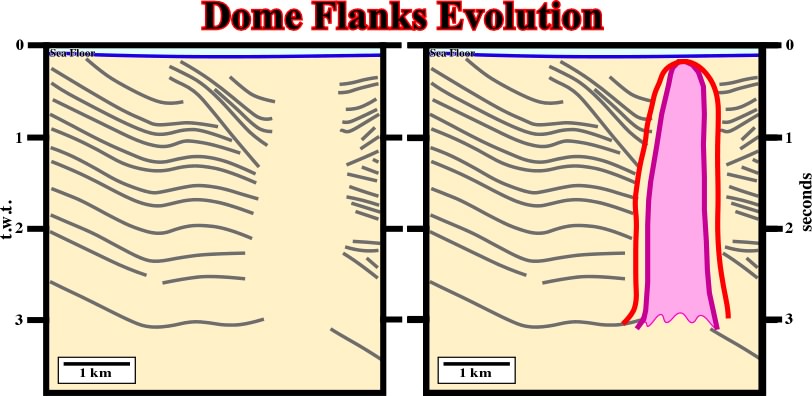
On this the evolution of the flanks of the dome is different. They are quite asymmetric, particularly the rim synclines. Note that as the line is unmigrated, interpreters have a tendency to increase the wideness of the dome (red picking instead green picking). On the other hand, firstly, it is quite evident that the dome cannot have vertical flanks (mechanical instability), secondly, taking into account the velocity of the seismic waves in the salt, a continuous column (3 seconds, t.w.t.) of salt corresponds roughly to 6-7 km of salt, which seems unlikely. |
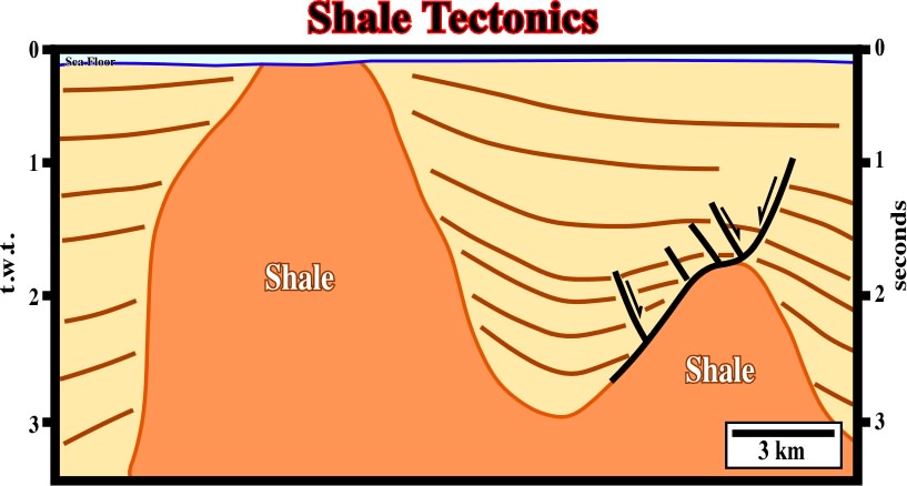
Without regional context and in isolation, very often it is quite difficult to decide if a detachment plane is associated with a salt or shale interval. This is particularly true when the bottom of the mobile substratum is not well individualized. This seismic line shows a typical association between shale and salt movements. |
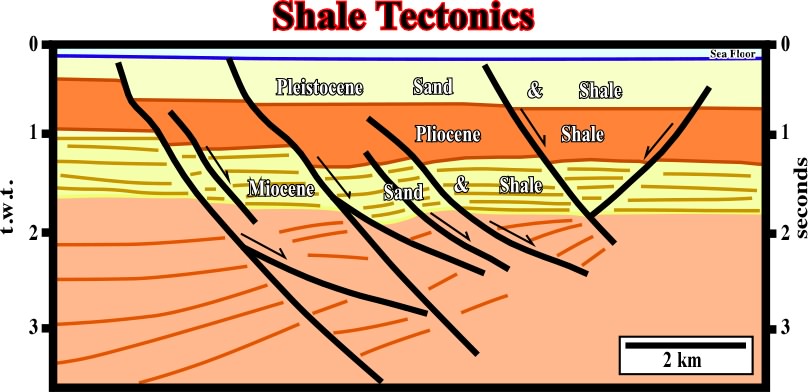
Two well-known areas, the Niger delta and the Gulf of Mexico, can be considered as typical shale tectonic areas. On this line from Niger delta, shale diapirs are more than evident |
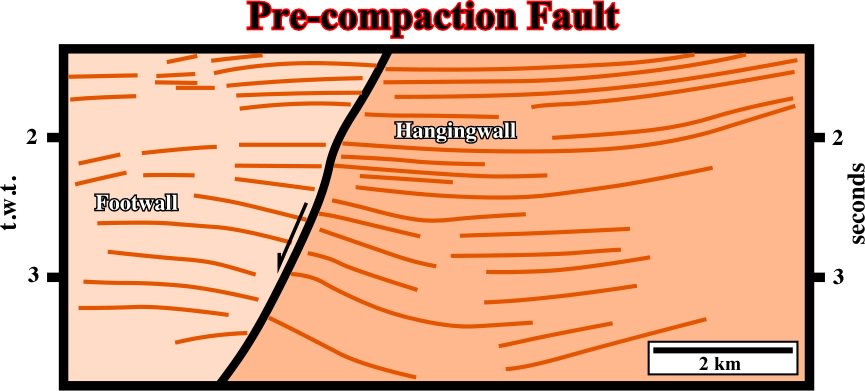
On this seismic line, it is easily to recognize that the majority of the faults are pre-compaction. Indeed, the dip of those fault planes chances with the compactability of the intervals. i.e., plus compactable is the sedimentary interval lower is the dip of the fault plane. |
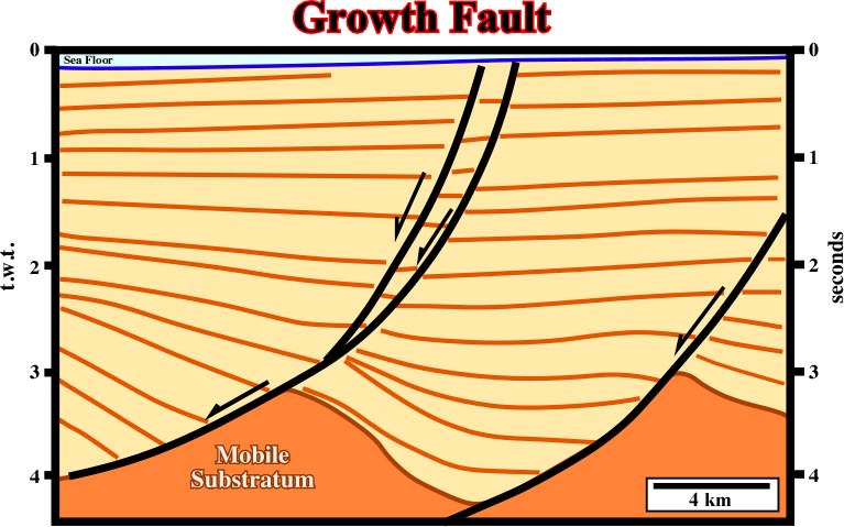
When a fault is active during deposition, it means that the downthrown block, rotates, and the fault plane becomes less and less steep with depth, due to a volume problem. |
The dip of a pre-compaction fault changes with the lithology. Higher is the dip of the fault less compactable is the juxtaposed sedimentary interval on the footwall (upthrown block). |
On this line, the fault in red is precompaction as suggested by the changes in the dip of the fault with the lithology. On contrary, the faults in blue are posterior. They do not correspond to really normal extensional faults, but to plane discontinuities between rotated blocks (splintering or "horsetail" of the fault). |


see http://plate-tectonic.narod.ru/kurpacificphotoalbum.html