 | Tectonic Regimes in Sedimentary Basins |
|
|
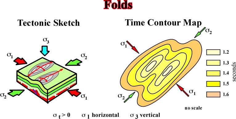
Fig. 119- Cylindrical folds are the structures created when a sedimentary basin is affected by a compressional tectonic regime with a 3 (minimum effective stress) vertical. The axes of these structures is parallel to 2. |
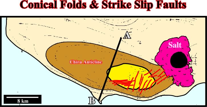
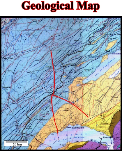
Fig. 120- The geological map of the Chiru anticline strongly suggests the axis of the anticline, i.e. the 1, is roughly parallel to the coast line. The presence of conjugated strike slip faults near the apex of the structure is also quite evident. Such a relatively small strike slip faults faults elongated the anticline along the axis. The line AB underlines the location of the seismic line illustrated on fig. 121. |
|
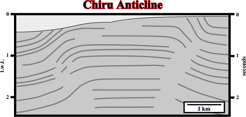
Fig. 122- On this seismic line, it is quite evident the sediments were shortened, and so uplifted by a compressional tectonic regime with s1 roughly parallel to the trace of the profile. The folding (concentric) was not sufficient enough to accommodate the sediments since reverse faults on the flanks of the anticline are easily recognized particularly on the right flank. On the contrary, the small strike slip faults allowing the lengthening of the anticline along the 2, recognize on the geological maps, seem to be under seismic resolution |
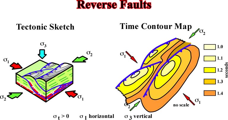
Fig. 123- Reverse faults develop during compressional tectonic regimes with 3 vertical. Strike roughly parallel to the 2, their traces are almost always in relay to respect volume problems. Indeed, a relatively large sedimentary area cannot be shortened by a unique fault. Faults in relay, as illustrated above are one of the ways to solve the volume problems pose by a single fault, were the maximum shortening is generally in the middle of the fault and nil at the its ends |
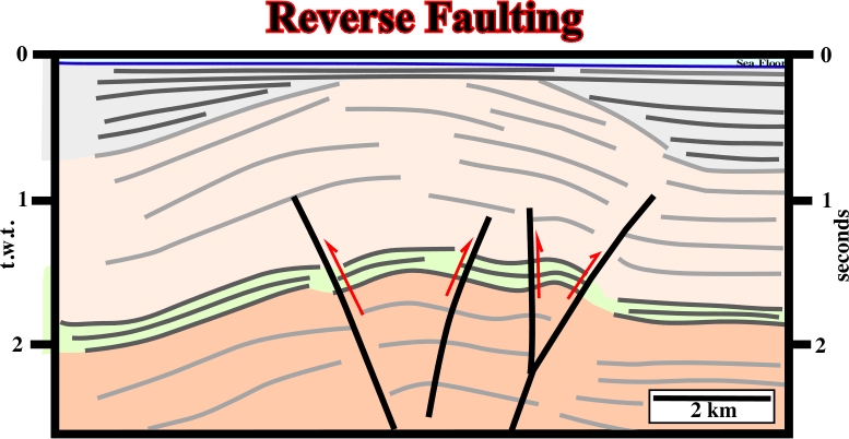
Fig. 124- On this line, the uplift of the sediments underlies a shortening created by a compressional tectonic regime with a 3 vertical. The shortening was made by folding (cylindrical folding) but also by reverse faulting. Indeed, on the right part of the line (around 1.8 s depth), a reverse fault, affecting a relatively high amplitude reflector, is easily recognized. A close look to the thickness of the seismic intervals allows to associated the reverse faulting to a major tectonic inversion. In other words, it is likely that the reverse faults corresponds to a reactivated pre-existent normal fault. Indeed, the thickness of the sedimentary intervals forming the hangingwall (upthrown faulted block) is higher than that of the footwall intervals. |
|
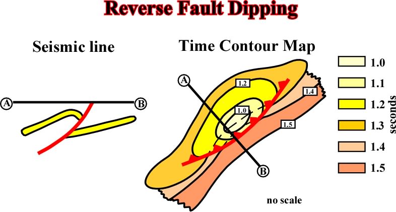
Fig. 125- This sketch is quite important and can avoid seismic interpreter to make mistakes. Indeed, when two fault blocks are evident on a seismic line, righthander interpreters (without tectonic knowledge) have a natural tendency to pick normal faults, i.e. faults with a fault plane dipping toward the dowthrown block. However, this sketch that them than when the shortening is located in the upthrown block, the fault is reverse since the fault plane dips toward the hangingwall. |
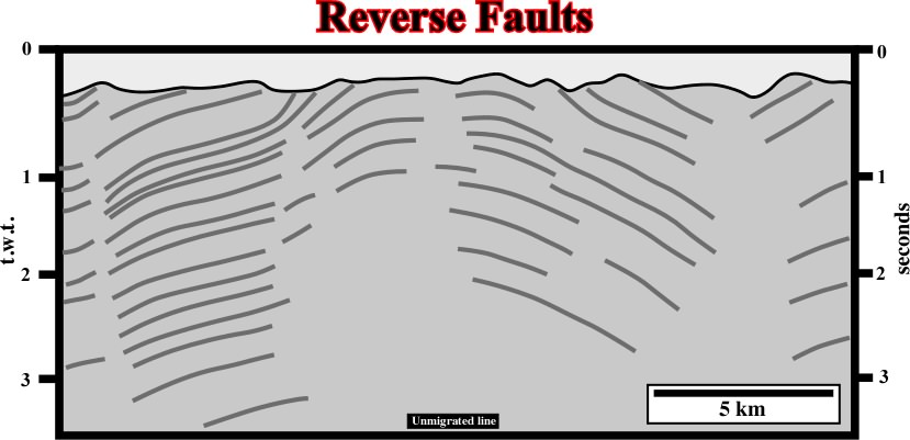
Fig. 126- On this seismic line, roughly paralle the 1, the sediments were shortened and uplifted. Several faulted blocks are easily recognized. Some of them are upthrown blocks and other downthrown blocks. A seismic interpreter knowing the basic principles of Tectonics takes the fault planes as reverse (only reverse faults can shorten the sediments). On the other hand, as suggested in the previous figure, the shortening is mainly realized on the upthrown faulted, so, the fault planes must dip toward the upthrown blocks, as it is the case in all reverse faults. On this subjects, it is quite important to understand that in the majority of the seismic lines there are no reflectors associated with fault planes. Actual, as depictecd on this line, a fault plane is just a mental construction underlying the discontinuity between the reflectors (chronostratigraphic lines) of the faulted blocks |
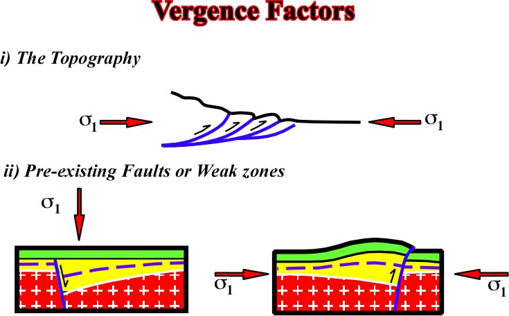
Vergence-Fig. 127- Topographic anomalies and heterogeneities of the substratum, often, control the vergence of faulting (normal and reverse). In the upper sketch, it is quite obvious the vergence of the reverse faults is controlled by the orientation of 3 and confining pressure. In the lower sketch, where two tectonic regimes took place, the strike and dip of the normal faults control the vergence of the faults during the late compressional tectonic regime. Actually, the pre-existing normal faults are reactivated during the compressional regime and the shortening is realized along the pre-existing weak zones. |
|
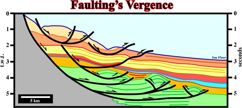
Fig. 128- The vergence of these listric faults is controlled by the water depth and associated confining pressure. In spite of the fact that, in the upper part of the fault planes, the movement is normal (extension), in the lower part (seaward), the movement is reverse. Indeed, in the toe of the fault planes, the sediments are shortened (local compressional tectonic regime) to counterpart the updip extension. Similar large scale examples are found in divergent margins with active shalokinesis or halokinesis. |
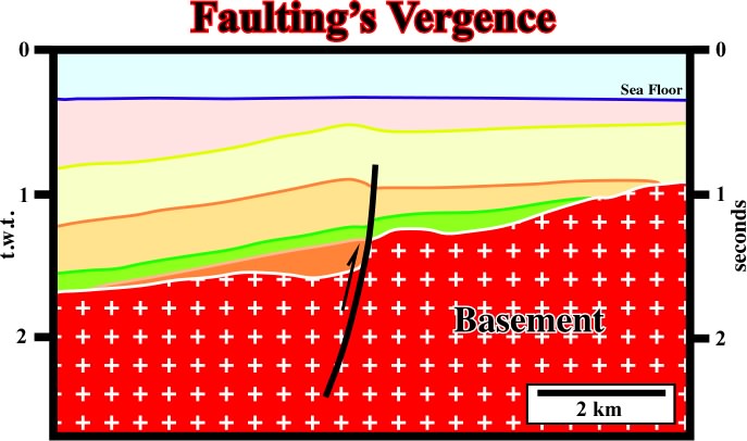
Fig. 129- In this example, a pre-existing normal fault, bounding a small rift-type basin, was reactivated during a later compressional tectonic regime. Taking into account the strike of the pre-existing fault and the strike of 1, during the compressional regime, it was easier to accommodate the sediments using the old fault plane than creating a new fault. So, one can say the vergence of the young reverse fault was controlled by the strike of the older normal fault. |
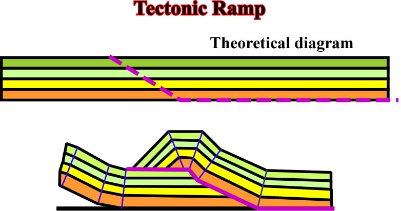
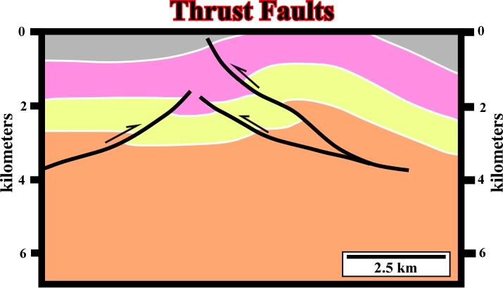
Fig. 130- On this theoretical model, high pressure levels (detachment plane) and pre- faults or weak zones exiting (ramp) can control shortening in thrust belt areas. |
|
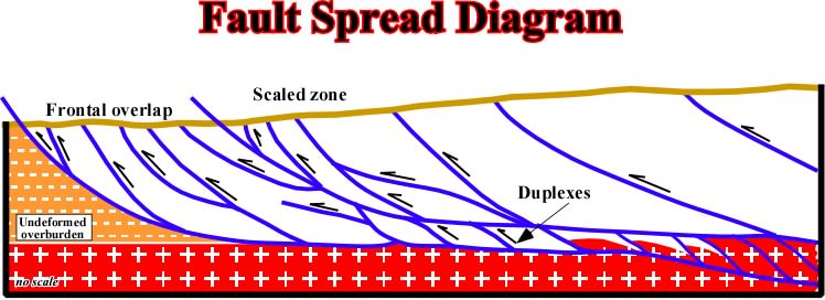
Fig. 131- In a thrust belt complex, faults planes are interconnected and related. Locally, duplexes structures are possible as illustrated above. |
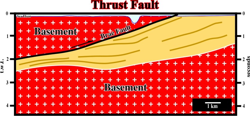
Fig. 132- A major thrust fault is recognized on this seismic line. Due to the geometry of a thrust fault, the hangingwall sediments are older than those of the footwall, and so, their density is higher, which gives, in time sections, a lateral change of velocity and the associated pitfall, i.e. a pull-up of the footwall sediment under the hangingwall. Subsequently, interpreters must be careful when a antiform structure is identified below a thrust fault plane in a time seismic line. Very often much of such structures are apparent and they no not exist in depth versions. |
Fig. 133- On this line, one can find the geological principle allowing identification of reverse faults: (i) the faulted blocks (downthrown and upthrown) are easily recognized by the associated seismic surfaces, (ii) the shortening is located in the upthrown block, (iii) the fault planes dips toward the upthrown block, (iv) the downthrown blocks are slightly tilted with minimum of shortening, (v) the topography of the ground corroborates the reverse faulting interpretation, i.e. the maximum shortening is the upthrown block: shortening induces uplift. |
|
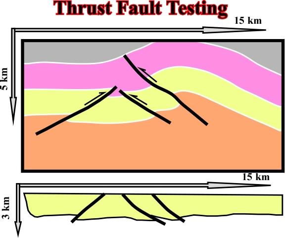
Fig. 134- In the geological interpretation of seismic lines, particularly those in a compressional setting, interpreter must take into account the Goguel''s Law. Indeed, the above interpretation looks very coherent. The folding seems concentric, and the dips of the reverse faults are in agreement with the Anderson''s Law (the seismic line is in depth and the scales are almost the same as in the field, i.e. 1:1). Nevertheless, In Science the truth doesn''t exist. So all seismic interpretation must be tested in a critical approach (see fig. 135). |
Fig.135- Testing the geological interpretation of the previous figure it is easily to recognized than it is easily falsified by the Goguel''s Law. Indeed, volume''s restorations using the software Locace indicates that the thickness of the yellow interval was not kept constant during deformation. A constant thickness of the yellow implies a quite different a different dip of the reverse fault planes. |
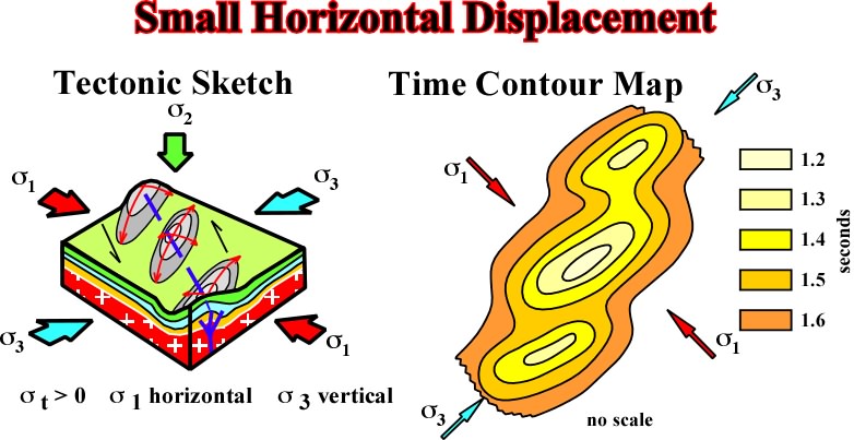
Compression Fig.136- In a compressional tectonic regime, when the basement is involved and the 2 is vertical, The lateral displacement of basement block creates a significant shortening in the sedimentary cover. Depending on the amount of lateral displacement of the basement blocks, the shortening can be done either by folding or by folding and faulting. |
|
Fig. 137- On this geological map, one can recognize (i) the strike slip faults displaced the folds (the geometry in each fault block is the same, (ii) the strike slip faults are pre-folding (the geometry of each compartment is different), (iii) some of the strike slip faults have an "en-йchelon" geometry, which implies a basement movement. |
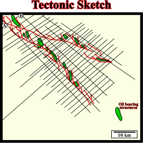
Fig. 138- This tectonic sketch, built-up with a relatively dense seismic grid, strongly suggests the oil bearing structures are, in fact, conical folds created by lateral displacements of basement blocks, which induce in the sedimentary cover complex strike slip faults. The cross section AB on the left upper corner of the tectonic sketch corresponds to a seismic line, which is illustrated on fig. 139. |
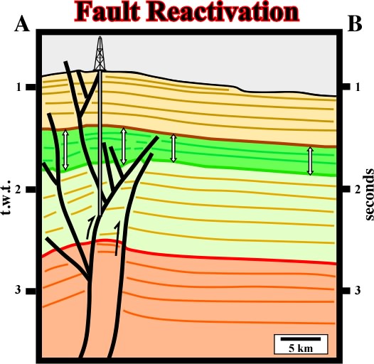
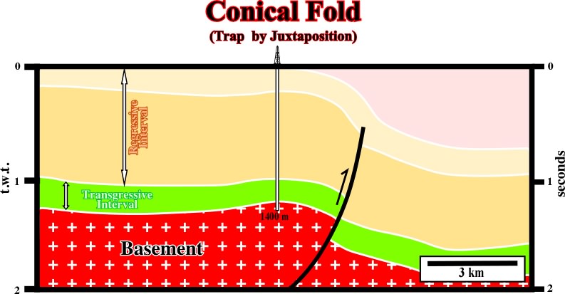
Fig. 139- On this seismic line, which is roughly perpendicular to s1 during the late compressional tectonic regime, it is quite evident that a pre-existing normal fault, recognized by the change in thickness in each side of the fault of the seismic interval bounded by the green and yellow reflectors, was reactivated as reverse fault. The shortening of the sediments is recognized by reverse faulting and folding (buckling). The folding is conical. Indeed, on parallel lines, the apex of the structures is progressively displaced toward or outward of the trace of the major reactivated fault. |
|
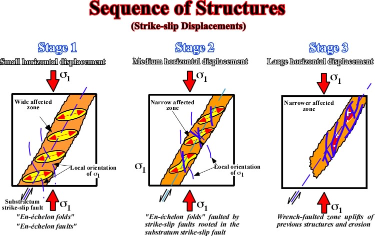
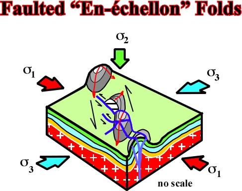
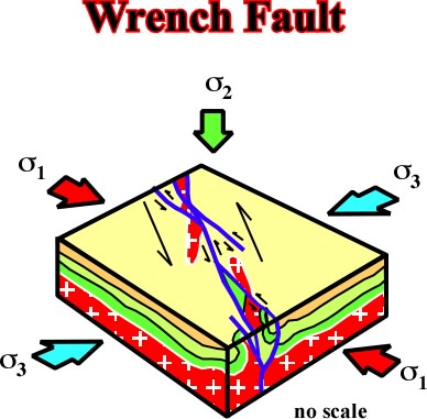
Fig. 140- As illustrated, the three major steps of deformation created in the sedimentary cover by an increasing strike-slip displacement of basement blocks are: (i) en-йchellon folds, (ii) faulted en-йchellon folds and (iii) wrench faults. As deformation progresses the area of deformation becomes narrower what implies a significant uplift (Goguel''s law). |
Fig. 141- En-йchellon folds are conical folds. Indeed, When plotted in a stereographic projection, they do not lie in a great circle, as the cylindrical faults, but in a small circle (parallel) with horizontal or dipping axis. |
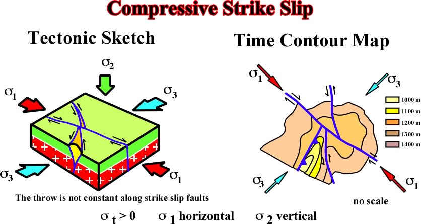
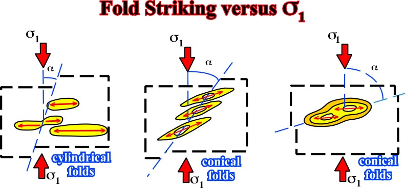
Fig. 142- The orientation and relationships between strike slip-faults and cylindrical and conical folds, can be summarized as following: (i) the vertical amplitude of the conical fold is often greater when increases, (ii) if is small, cylindrical folds are not associated with the fault, (iii) generally, the smaller is, the more the fold axis plunges to the immediate vicinity of the strike-slip, (iv) average plunging values are between 20є and 70є. |
|
Fig. 143- In this particular example, as lateral displacement increases shortening cannot be done just by folding. The axes of anticlines are displace"d by strike slip faults. Subsequently, the plane of the strike-slip faults become essential for "up dip" closure. The associated traps are no more structural as in "en-йchellon folds, but morphological by juxtaposition. |
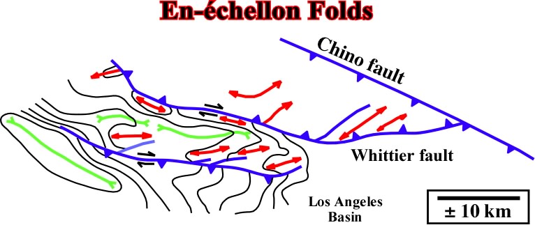
Fig. 144- In spite of the fact that some of the traps associated with the en-йchellon folds in Los Angeles basin are morphological by juxtaposition, one cannot say that the majority of the structures correspond to faulted en-йchellon structures. Indeed, as illustrated in this sketch the structures are typical en-йchellon folds induce by the movement of the main strike slip faults. |
Fig. 145- This seismic line was initially picked in extension (1973), i.e. the fault plane individualizing the fault blocks was dipping toward the dowthrown block. However, since interpreter notice that the shortening, and uplift, was mainly in the upthrown block, immediately the structure was considered as compressional. Subsequently the fault was picked as reverse with the fault plane dipping toward the upthrown block as illustrated. In addition, the mapping of the fold located on the hangingwall showed that its geometry was conical, since axial direction is oblique to the strike of the fault. |
|
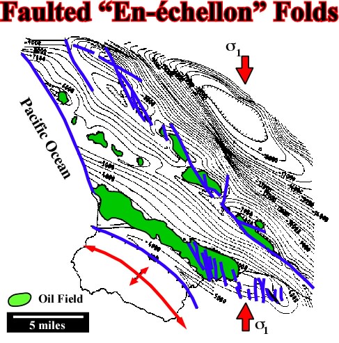
Fig. 146- On this map, the majority of the hydrocarbon traps are morphological by juxtaposition, i. the hydrocarbons are laterally trapped by sealing rocks that the movement of the faults planes put in juxtaposition with the potential reservoirs rocks. In spite of the fact that these traps are known by some as fault traps, it is important to say that a fault never traps, what traps is the rocks in the other side of the fault (in juxtaposition with the reservoir) or the rocks filling the gauge zone. |
Fig. 147- "San Andreas fault" is one of the most studied examples of this kind of faults. Basement outcrops are well seen near the fault zone and the oil bearing basin is located at more than 50 km eastward, where "en-йchelon folds" and faulted "en-йchelon" are developed. The area of deformation became narrow and uplifted. |
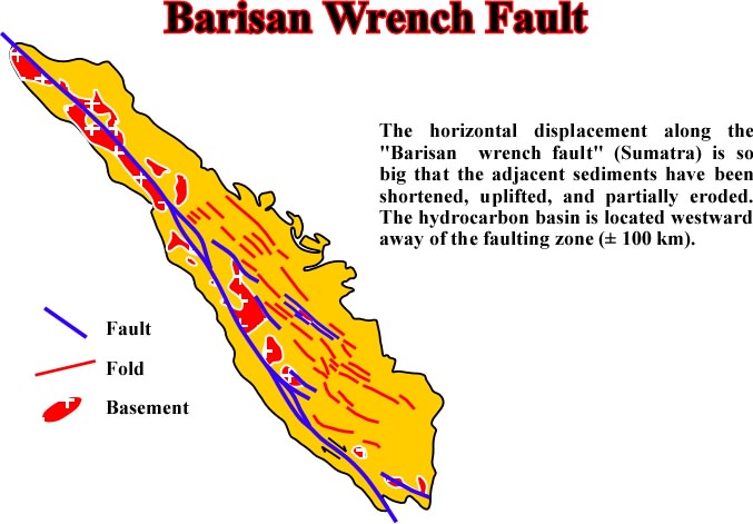
Fig. 148- In Barisan fault, the lateral displacement of the basement fault blocks is so big, that blocks of the basement were uplifted and form large outcrops all along the area of deformation. Westward of the major wrench fault the prospectivity of the sedimentary basin is not only due to the presence of excellent source rocks by the large number of traps associated with en-йchellon folds |
|
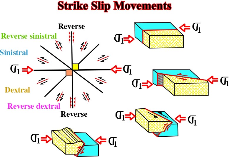
Fig. 149 - When sediments are deformed, in compression or in extension, all pre-existent structures are reactivated during new tectonic regimes. Assuming there are inheritated structures striking in all direction, their reactivation depends mainly of the angle between their strike and the new 1. Thus, when the angle is near 90║ the fault will be reactivated as reverse, if the angle is near 45║, it will be reactivated as sinistral, etc.. |
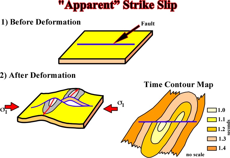
Fig. 150- The presence of a pre-existing fault zone or a weak zone can apparent displaced new formed structures. Indeed, in this particular example, both blocks of the pre-existent fault were deformed independently, creating two more or less parallel anticlines, but not to anticlines rejected, since the fault zone is pre- and not post-deformation. Such mechanism can explain several "strike slip faults" in onshore Venezuela, as the Urica or Anaco fault. |
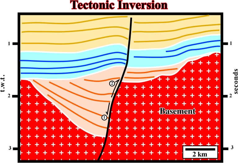
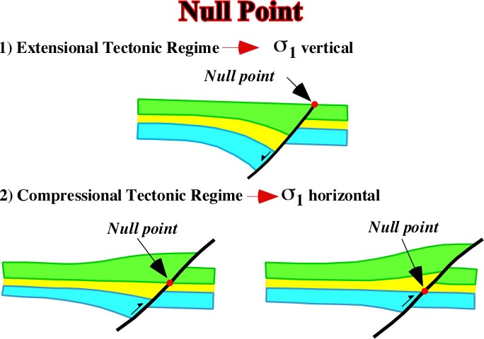
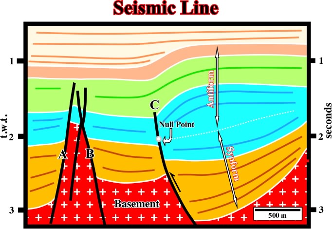
Fig. 151- On this seismic line, a tectonic inversion created by the reactivation of pre-existing extensional structures is quite evident. The pre-existing normal fault of the hal-graben rift-type basin, was later reactivated as reverse fault during a compressional tectonic regime. Taking into account that the tectonic inversion was not total, two geometries can be recognized along the fault plane: a normal geometry in the lower part and a reverse geometry in the upper part of the fault plane. These geometries are separated by a point where apparently there is no displacement- the null point. |
|
Fig. 152- Below the null point the geometry of the fault is that of a normal fault, while above, the geometry is that of a reverse fault. The position of the null point on the fault plane depends of the amplitude of the inversion. Higher is the null point smaller is the inversion. When the null point is on the bottom of the fault plane, the inversion was total, and so only the reverse geometry is recognized. |
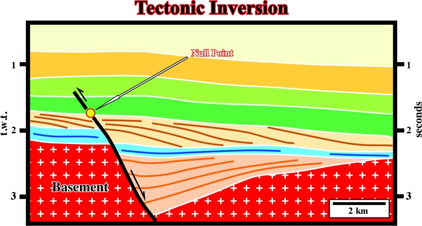
Fig. 153- On this North Sea line, the null point is located on the upper part of the fault plane: (i) It limits a normal geometry below it, where the sediments still seems lengthened, from a normal geometry, where the sediments are slightly folded, (ii) the tilted fault blocks developed during an extensional tectonic regime, are sealed by transgressive sediments which underlying a progradational interval, (iii) these intervals, which can be identified on the hangingwall and the footwall, allow stratigraphic correlations and the calculation of the fault displacement. |
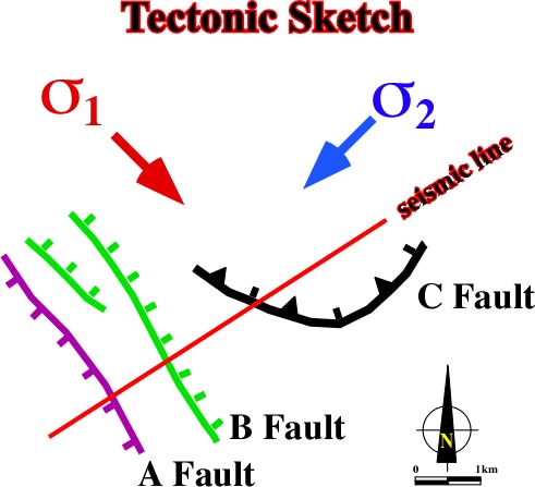
Fig. 155- On this tectonic sketch there are three faults belonging to quite different tectonic regimes. They have different direction, Subsequently, when the area will be affected by a new compressional tectonic regime, they will be reactivated in different ways as corroborated by the seismic line illustrated in fig. 155. |
|
Fig. 156- This seismic line corroborates the fact that only the fault C, which strikes roughly perpendicularly to the new 1, was reactivated as reverse fault creating a sharp tectonic inversion. |
Fig. 157- The pre-existing grabens bounded by normal faults dipping 60░ and striking perpendicularly to 1 were not favorable for reactivation. Subsequently a new reverse fault, perpendicularly to 1, was created. |
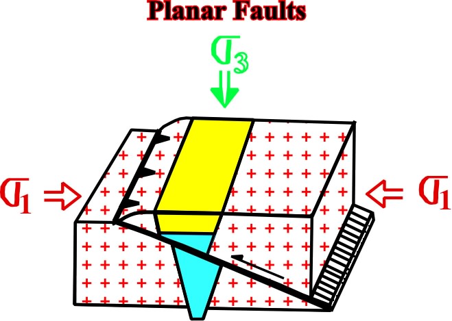
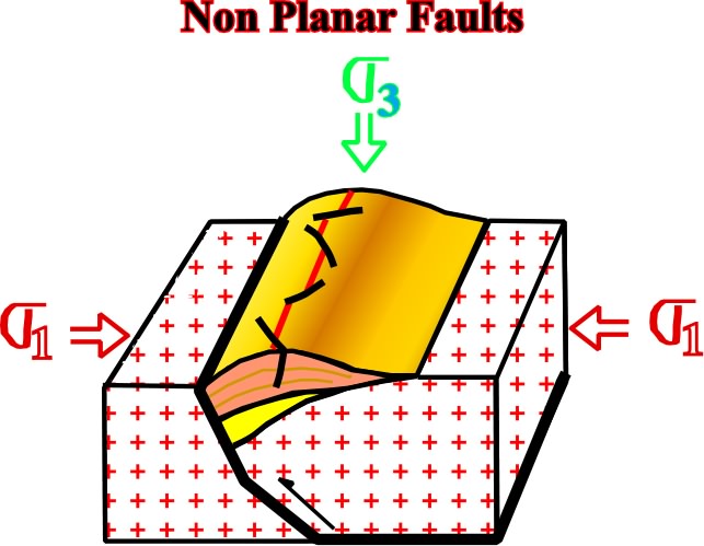
Fig. 158- In non-planar normal faults, the deepest part, with a dip of 45░ or less, is far from the optimum conditions for reactivation. Contrariwise, the shallow part having a high angle can not easily be reactivated and inversion, by buckling and folding, occurs above the fault plane. Consequently, as illustrated, two opposite geometries can be recognized. In the lower part a synforme geometry and in the upper part an antiforme geometry. |
|
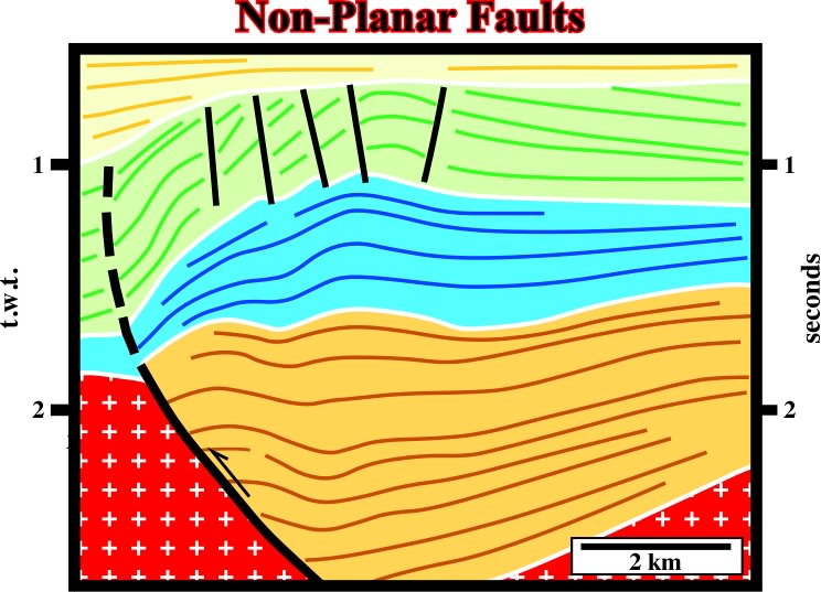
Fig. 159- One can say the lower part of this non-planar faults was reactivated by inversion, i.e. the sediments were shortened by a reverse movement of the pre-existing normal faults, whereas as in the upper level, the sedimentswere shortened by folding. Consequently, in the upper sediments, i.e. those shortened by folding, it is normal to find small strike slip faults near the apexes of the anticlines. These strike slip faults allow the lengthening of the sediments along 2, as a counterpart of the shortening along 1. |
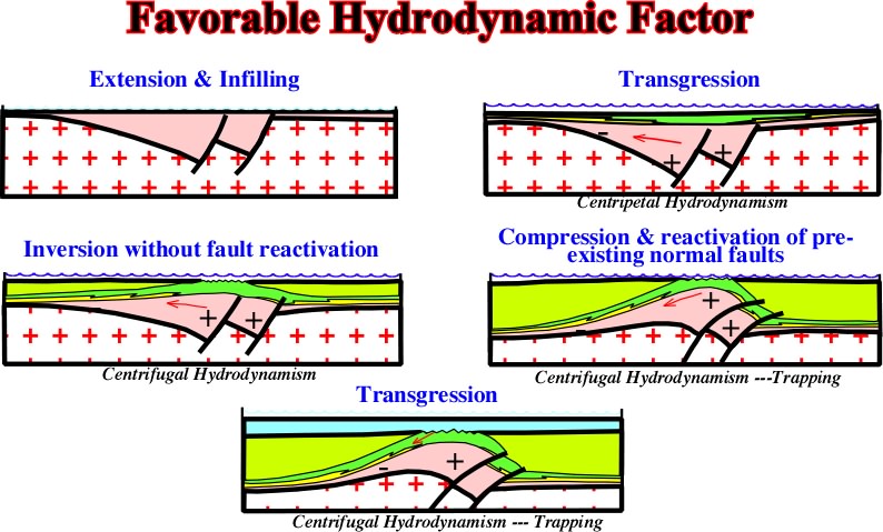
Fig. 160- During extensional tectonic regimes, the hydrodynamism is centripetal. However, as tectonic inversions took place, the high structural points become low points and the low structural points become high points, and so, centrifugal hydrodynamism becomes preponderant. Subsequently, hydrodynamism being down dip enhances the possibility of non-structural trapping, particularly the stratigraphic traps associated with the transgress if intervals, as illustrated on the next seismic line (fig. 161). |
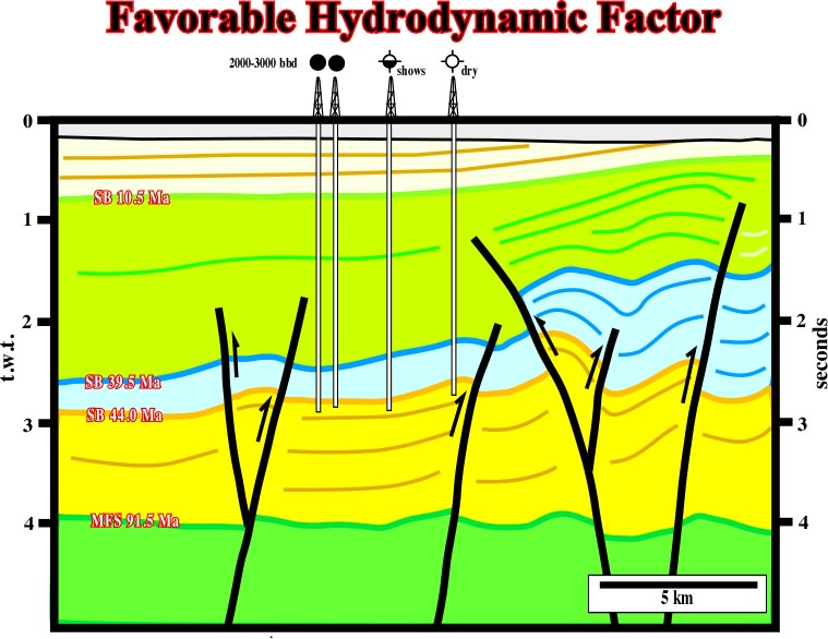
Fig. 161- The location of the wells with hydrocarbons corroborates the hypothesis that the accumulations are associated with non-structural traps (stratigraphic) in which the trapping is enhanced by a strong down-dip hydrodynamic factor. |
Contents:
5.1- Basement Involved
5.1.1- Compression (1 horizontal)
5.1.1.1- Folds & Thrusts
A- Folds
B- Reverse Faults
C- Thrust Belts
5.1.1.2- Compressive Strike-Slip
A- Small horizontal displacement (1-5 km)
B- Medium horizontal displacement (5-20 km)
C- Large horizontal displacement (20 km)
5.1- Basement Involved
5.1.1- Compression (l horizontal)
5.1.1.1- Folds & Thrusts
- Basement Involved
5.1.2- Extension (1 vertical)
Generalities
a) Sequence of geological events
b) Dip of beds and dip of faults
c) Angle between the fault plane and the vertical
d) Depth of a detachment surface
e) Amount of extension
f) Ends of a normal fault
g) Normal faulting deformation
h) Intermediated fault blocks
i) No planar faults
j) Deformations in no planar faults
k) Associated grabens
5.1.2.1- Positive Tectonic Stress (t > 0)
a) Normal Faults - Grabens
b) Pull-apart Basins (Local stresses)
5.1.2.2- No Tectonic Stress (t = 0)
5.1.2.3- Negative Tectonic Stress (t <0)
a) Rift-type basins & Grabens
b) Continental margins divergent
c) Differential subsidence
d) Differential uplift
e) Transfer basins
Basement Involved: Extension.....Lengthening.....Subsidence.....RSL Rise.....Sedimentation
Faults