 | Salt Tectonics, Diapires and Transfer Basins |
|
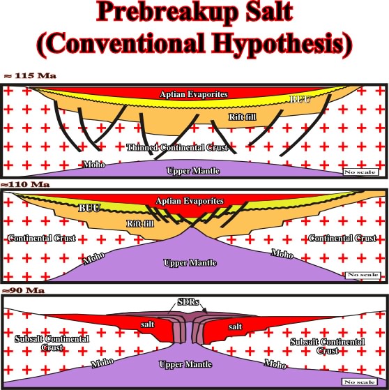
Fig. 215- This hypothesis has several implications: (1) rifting took place both before and after salt deposition; (2) conjugate salt basins were originally a single giant salt basin that was later divided by continental breakup; (3) the breakup unconformity should overlie the Aptian salt, but this is not observed; (4) evaporites were thickest in the center of the giant salt basin, above breakup zone, but this is not observed; (5) after breakup, the oceanward edge of salt basin is abrupt, fault-bounded margin through thickest salt, but this is not observed; (6) basalts should sink into thick distal salt until they froze and strengthened, but this is not observed; (7) seaward-dipping reflectors should overlie distal salt basin, but this is not observed. |
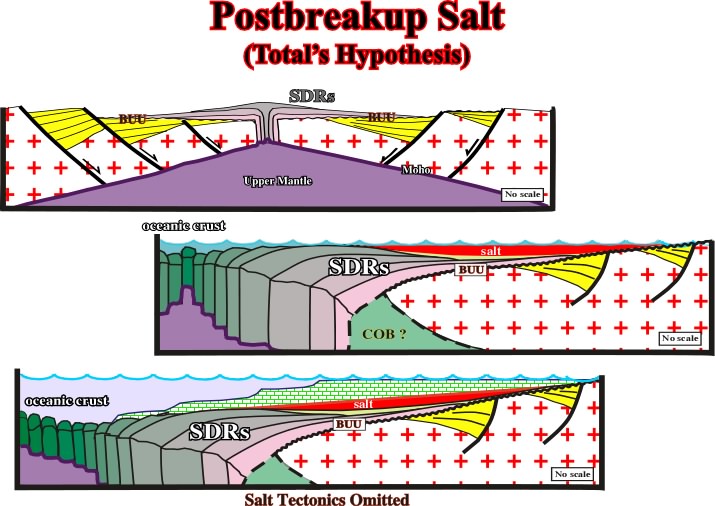
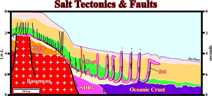
Fig. 216- On this hypothesis: (1) rifting ended before salt deposition; (2) the Aptian salt overlies the break-up unconformity (observed on seismic lines); (3) conjugate salt basins were always separate and independent; (4) oceanward edge of salt basin is a pinch-out of thin salt, which creates a toe-thrust that may be thickened by later salt flow (observed on seismic lines); (5) seaward-dipping reflectors should underlie the distal salt basin or its age equivalent. This is observed wherever seaward-dipping reflectors have been identified |
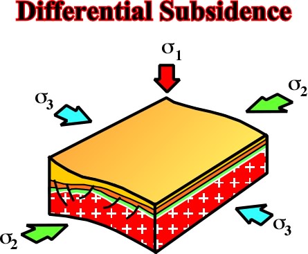
Fig.217- Near the hinge line of a basin, a local extension tectonic regime is often created, which oblige the deposited sediments to lengthen along to s3 forming grabens (not rift-type basins) striking parallel to the hinge line (s2), as illustrated in fig. 218. |
|
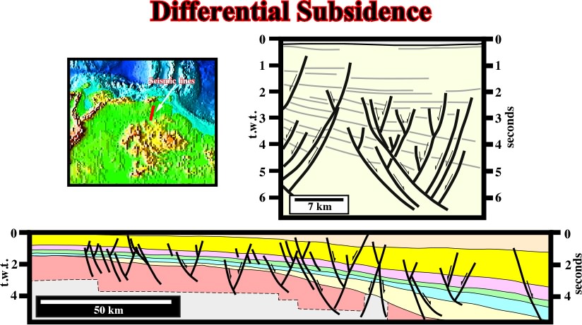
Fig. 218- In onshore Venezuela a lot of oil accumulations are associated with graben striking parallel to the hinge line of the basin. Indeed, around the hinge line, the sediments were lengthened by normal faults, with opposite vergences, developed parallel to the hinge line. |
Fig. 219- Vertical movements, i.e., apparent vertical movements are just a consequence of folding and the elementary tectonic feature fault does not mean a special rupture along the earth''s radius but a rupture due to the lack of plasticity of a brittle "BATI" under horizontal tectonic stresses. Therefore epirogenic movements can be considered as folds with a very wide wavelength |
Fig. 220- As illustrated on this seismic line (Sevier Desert), the footwalls may remain unrotated while other parts may rotate in opposite directions over a low-angle normal fault. |
|
Fig. 221- As said previously, transfer basins are often the result of the extensional reactivation of pre-existent faulted zones. Therefore, they strike obliquely to 2. |
Fig. 223- In spite of the fact that the basins strike in different directions, the cross-sections are quite similar. Subsequently, on a single seismic line (fig. 224) it is quite impossible to differentiate transfer basins from "normal basin" (normal grabens). |
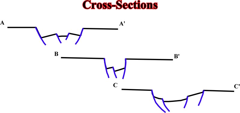
Fig. 222- On this sketch, the section AA'' and CC'' are located in what one call normal extensional basin (striking parallel to 2, while the section BB'' cuts the transfer basin (oblique to 2). |
|
Fig. 224- On this seismic line from the Tanganyika Lake, one cannot say if it corresponds to a transfer basin or to a normal graben. Such a differentiation requires to known how the faults strike in relation to 2. |
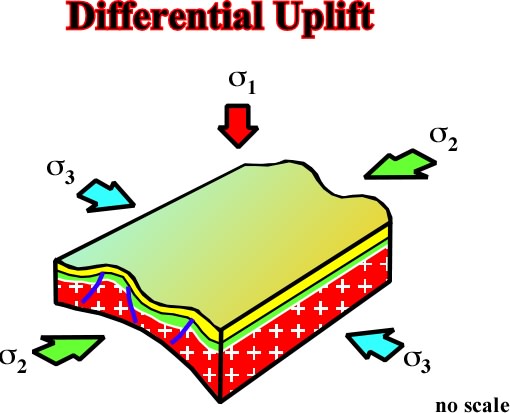
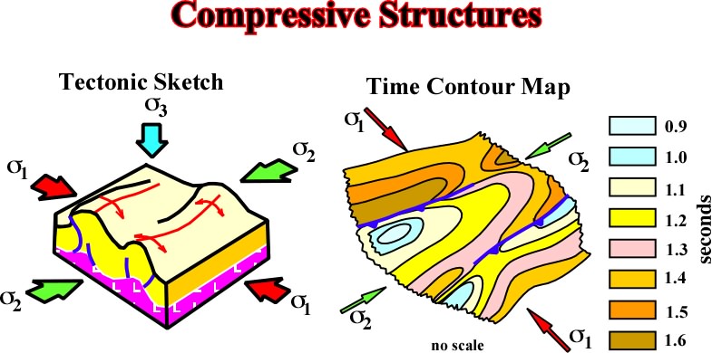
Fig. 225- The salt and cover can be shortened independently of the substratum. All kind of compressional structures can be developed as illustrated on the following figures (fig. 226 to 228). |
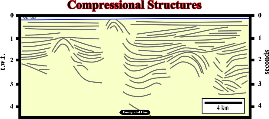
Fig. 226- Several compressional salt structures (anticlines, reverse faults), detached from the basement can be recognized on this seismic line from south onshore France. |
|
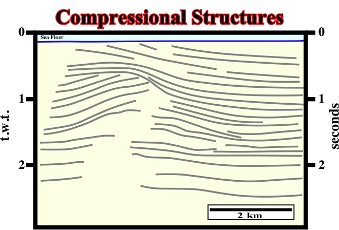
Fig. 227- A major tectonically enhanced unconformity separates two tectonic realms. The older one was compressional. The salt layer and its cover were strongly shortened and uplifted creating a major erosional surface, which underlies a significant stratigraphic cycle boundary. In this particular line, it is difficult to see is the basement is or not involved on deformation. Notice that on seismic lines the bottom of the salt layer usually shows a velocity anomaly (pull-up). |
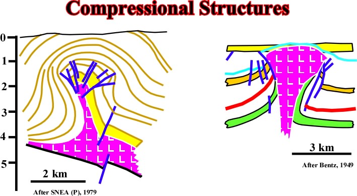
Fig. 228- Typical examples of compressional salt structures are known in Aquitaine basin (Eocene compression) and in South North Sea, where reverse faults develop in post-salt intervals. |
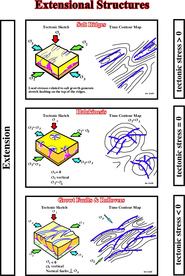
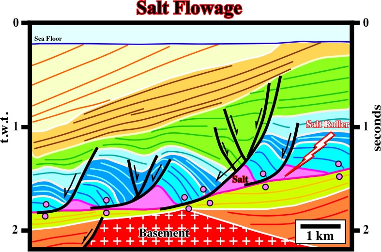
Fig. 230- With a tectonic stress nil, i.e., in absence of a major tectonic stage, the halokinetic movements can be very important. Usually they are synchronous of sedimentation, and so, they can partially control the facies and thickness of sedimentary units. With a negative tectonic stress, salt movements can produce salt ridges parallel to regional 2, growth faults, rollovers and gravity sliding structures. As halokinesis (t = 0) is almost always associated to salt ridges, growth faults, rollovers and gravity sliding structures, for genetic, and pedagogical reasons, we prefer to study all salt tectonic deformations together. Salt ridges associated with t < 0 are too similar to be studied separately. |
|
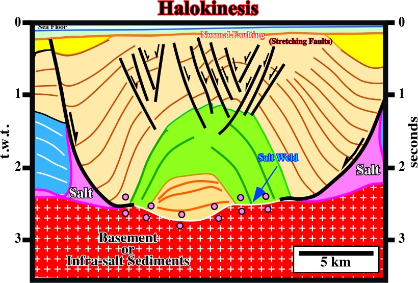
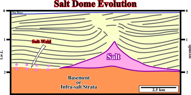
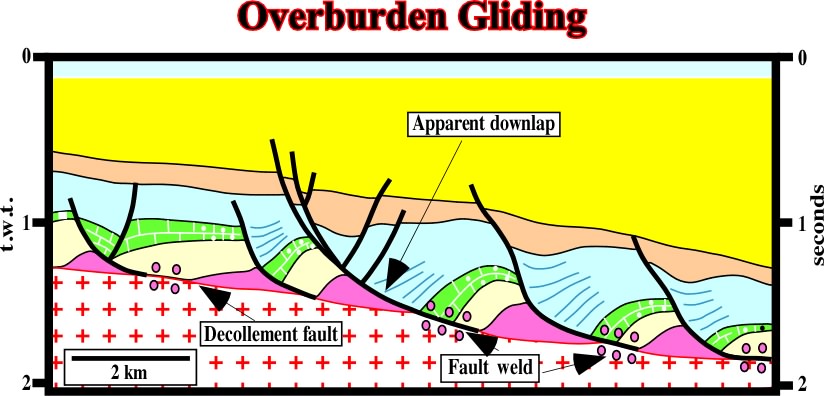
Fig. 231- Halokinesis takes place when tectonic stress is nil. Indeed, as illustrated on this seismic line, the pristine geometrical relationships where completed deformed by salt flowage, i.e., original onlap became apparent downlaps. The evaporitic layer became almost exhausted (salt weld). Salt is just recognized filling the lower part of the normal faults bounding the inverted depocenter. |
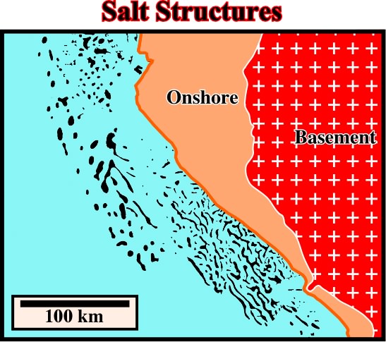
Fig. 232- Different morphologies of the salt structures are easily recognized in Gabon Offshore. The linear geometry, recognized in the southern part suggests (i) the irregularities on the salt surface are controlled, or (ii) salt tectonics mechanism is different of the described above. |
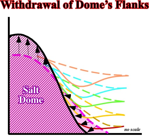
Fig. 233- As the salt moves from the flanks toward the crest of the dome, prekinematic sediments collapse and a local compensatory subsidence is created. Synkinematic sediments are thicker on the flanks than on the top of the dome. |
|
Fig. 234- On this seismic line from conventional offshore Angola, the rim synclines (depocenters) around the salt dome strongly suggest the compensatory subsidence, induced by salt flowage) is greater in the deepest part of the interface salt-overburden. |
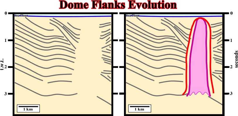
Fig. 235- On this the evolution of the flanks of the dome is different. They are quite asymmetric, particularly the rim synclines. Note that as the line is unmigrated, interpreters have a tendency to increase the wideness of the dome (red picking instead green picking). On the other hand, firstly, it is quite evident that the dome cannot have vertical flanks (mechanical instability), secondly, taking into account the velocity of the seismic waves in the salt, a continuous column (3 seconds, t.w.t.) of salt corresponds roughly to 6-7 km of salt, which seems unlikely. |
Fig. 236- On this regional line of offshore Brasil, growth faults and reverse faults are associated with salt tectonics. However, the reverse faults, located in the distal part of the basin, are associated with a local compressional tectonic regime created as a response to the updip extensional tectonic regime responsible by the growth fault development. |
|
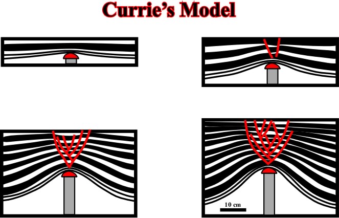
Fig. 237- The layers are lengthened by radial stretching faults as the piston moves upward. When the layers are synchronous of the piston movements, they thin upward. Theoretically, in a cross-section, the sum of the throws with opposite vergence must be roughly zero. |
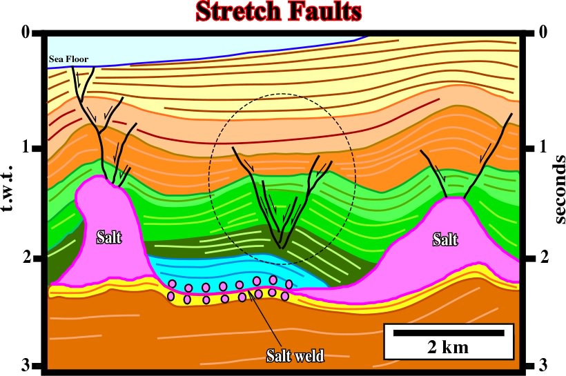
Fig. 238- Generally, stretch faults are radial when associated with domes. When associated with salt ridges and turtle back structures (elongated antiforms) as it is the case on this seismic line, the geometry of the stretch faults is mainly elongated. Indeed, on this seismic line, the stretch faults on the top of the central antiform are induced by the salt flowage toward the top of the ridges,which created a salt induced tectonic inversion. |
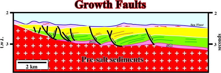
Fig. 239- In deep water Mediterranean Sea, growth is faults induced by flowage of Messinian salt are paramount. As suggested by this seismic line, the salt movement seems to be contemporaneous with the deposition of the yellow interval. The more or less constant thickness of the green interval suggests it is likely a prekinematic layer. |
|
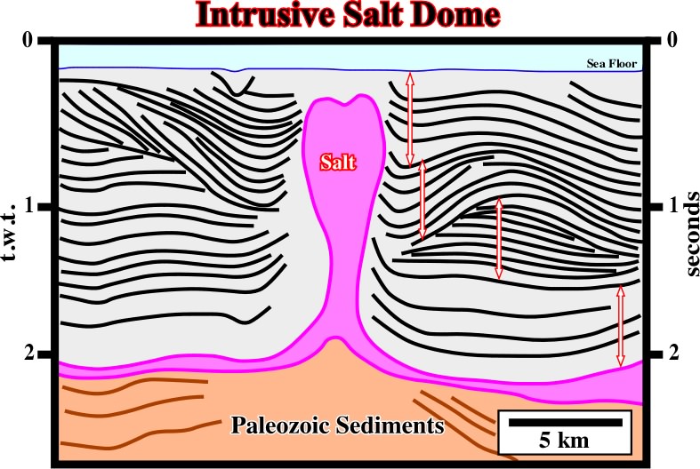
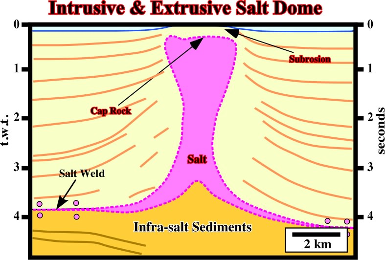
Fig. 240- On this sketch, it is easy to differentiate diapirism (on the left) and apparent diapirism (on the right). In fact, when a salt dome arrives in surface or at bottom sea, if it is connected with the source layer, the salt moves upward as sedimentations takes place. A tectonically enhanced unconformity underlines the salt outcropping. Indeed, below the unconformity, the postkinematic overburden is deformed by salt diapirism, but above it, the synkinematic overburden is undeformed since the salt moves upward at same time that deposition takes place (see fig. 241). |
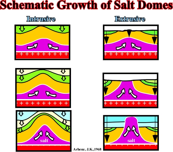
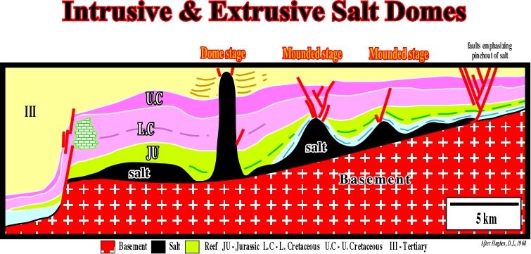
Fig.241- On this crosse section from onshore-offshore Alabama (USA),based on a regional seismic line, the salt layer (in black), which pinchout is underlined by a stretch fault complex, shows different phases of growth. In mound stage, one can say the structures are intrusive, but in the dome stage, they are extrusive with apparent diapirism in the upper layers (Upper Cretaceous and Tertiary). |
Fig. 242- In this unmigrated seismic line, the limits of the salt are difficult to pick. Nevertheless, the rim synclines of the upper intervals strongly suggest they are synkinematic. The more likely is that the salt is intrusive and probably disconnected of the mother source layer. The enhanced unconformity seems to be associated with the beginning of the salt flowage inducing significant compensatory subsidence and not with the arrival of the salt in surface as it is the case in the line below (fig. 243). |
|
Fig. 243- On this line the flanks of the salt structure are also quite difficult to pick. Nevertheless, the deformation of the lower overburden contrasts with the undeformed or slightly deformed upper overburden. The unconformity bounding deformed and undeformed overburden underlines the limit between intrusive and extrusive situation. So, one can say the upper salt shows apparent diapirism. |
Fig. 244- Likely, on this seismic line the allochthonous salt structures are disconnected of the mother salt layers. A vertical salt weld is probably present. We guess the salt arrives to bottom of the sea and started to move upward under an apparent diapirism. Then, when ii became disconnected of the mother layer (horizontal salt welds), the upward movement of the salt created a secondary vertical salt weld. |
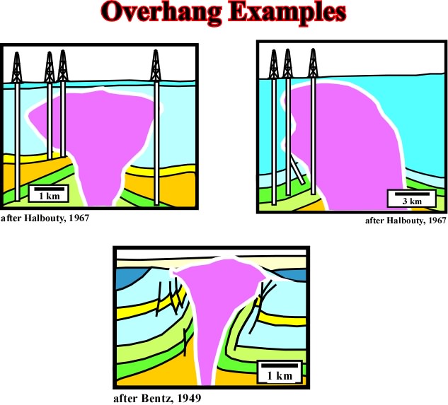
Fig. 246- Overhang examples after different authors. Note that in certain condition reverse, or apparent reverse faults can be developed in association with overhang geometries (see seismic examples below). |
|
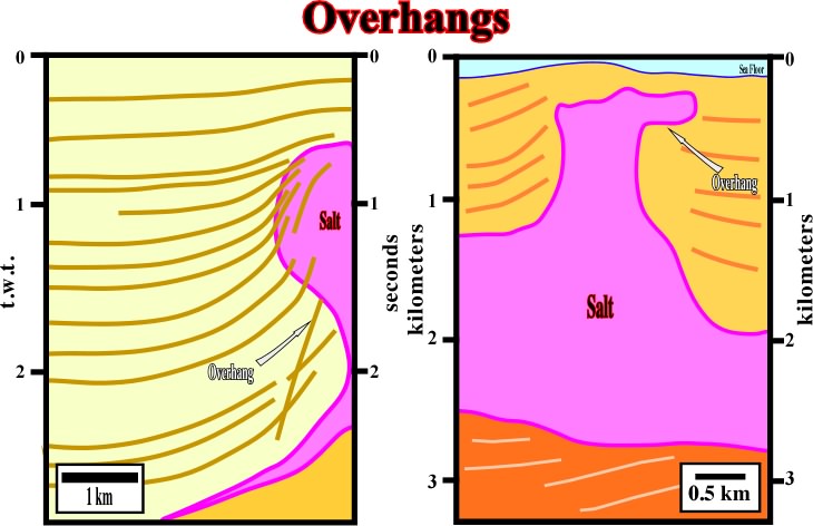
Fig. 247- Two examples of overhangs in time and in depth. The example in depth, coming from Gulf of Suez is more significant since the salt flow laterally in surface for almost 1 km. The example in time, from Gulf of Mexico, corresponds more to a salt bulk above a stem. |
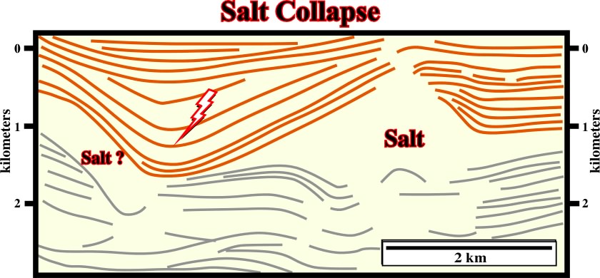
Fig. 248- The lateral flowage (salt withdrawal or salt collapse)of the salt created a local compensatory subsidence, which explains the depocenter overlying an old salt induced structural high. Between salt collapses interesting antiform structures can be developed as depicted in fig. 249. |
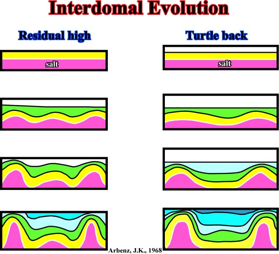
Fig. 249- As illustrated antiform structures, that is to say extensional structures can be developed between rising salt domes. Often, residual salt structures can be found in the heart of the interdomal structures. When salt expulsion is total, salt welds are created below the salt induced inverted antiforms. |
|
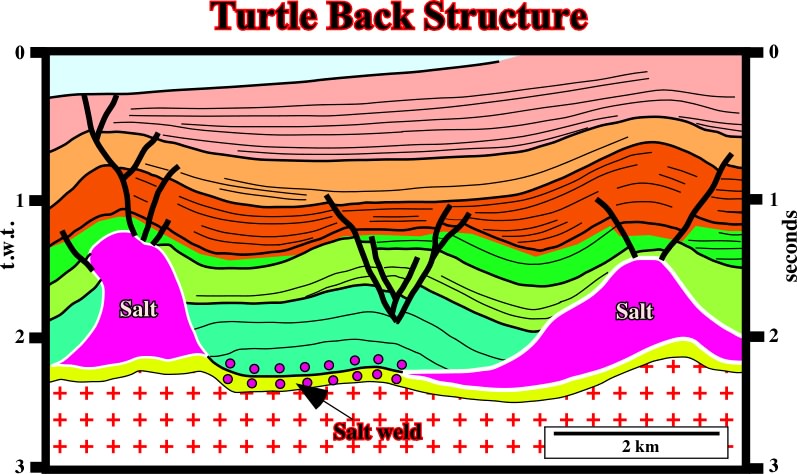
Fig. 250- On this time cross-section (interpretation of a seismic line), an asymmetric turtle back structure, developed between to salt domes, overlies a salt weld. Notice that the sediments associated with the brown interval strongly thick above the right dome. Such a thickness variation suggests the right salt dome was reactivated inverting the depocenter. The reactivation can be salt or tectonically induced. The apex of the turtle back structure was clearly extended by stretching faults. |
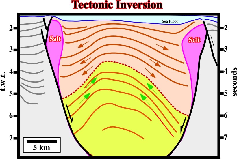
Fig. 251- Taking a look for the thickness of the seismic packages, it is quite easy to recognized the tectonic inversion and its timing. A major unconformity underlies the onset of the salt induced tectonic inversion. Before the inversion, the sedimentary intervals thick inward. Since inversion takes place, the sedimentary intervals thick outward, in direction of the salt domes, creating rim synclines. |
Fig. 252- On this line of the conventional Angola offshore the tectonic disharmony associated with the bottom of the salt layer is easily recognized; above it the sediments are significantly deformed, while below, rhey are roughly undeformed. The normal faults associated with the salt flowage can also be easily picked when taking into account the reflection terminations (seismic surfaces). The onset of salt flowage is underlined by an unconformity characterized by sedimentary intervals with internal configuration divergent above, and sediments with parallel internal configuration below |
|
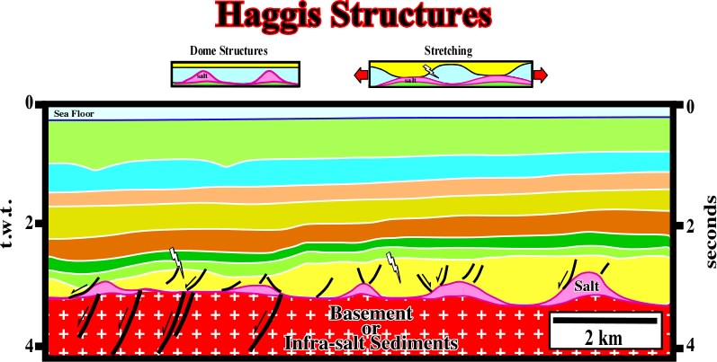
Fig. 253- As the name suggested, Haggis structures are inverted depocenters induced by a almost total salt reduction, This structures are quite frequent in North Sea and some of them have been drilled for hydrocarbons. The timing of inversion in relationship to the hydrocarbon migration time is an exploration key parameter. |
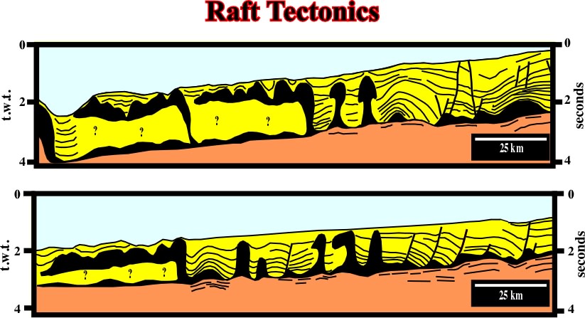
Fig. 254- The geological interpretation of the old (1968) seismic lines of the Northern Offshore Angola, raft tectonics ("Tectonique en Radeaux") is paramount. Several mechanisms have been propose to explained the morphology of the Tertiary depocenters and associated Cretaceous antiforms (fig. 255). |
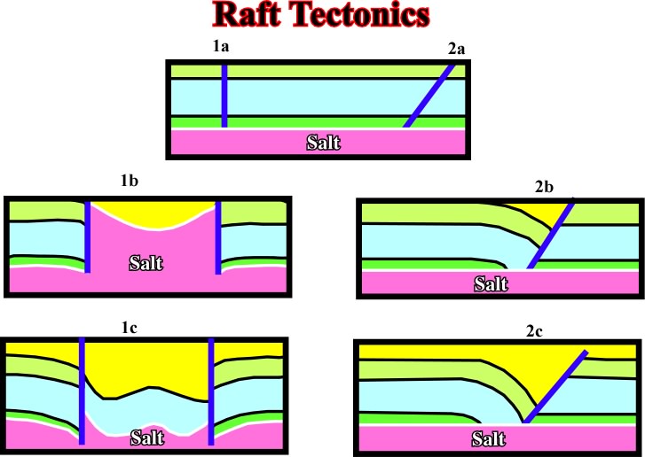
Fig. 255- Assuming a seaward gliding of a faulted overburden different kind of depocenters (in yellow) can be developed. A generalized seaward tilting of the cover (salt + overburden), often associated with the breakup of the Pangea lithosphere, must be taken into account. |
|
Fig. 256- The seaward gliding of the cover (salt + overburden) seems evident. The prekinematic overburden (light yellow interval) shows a slightly regional landward thickening, while the synkinematic overburden shows a strong landward thickening against the listric fault planes. Notice the formation of small fault welds between the salt rollers. |
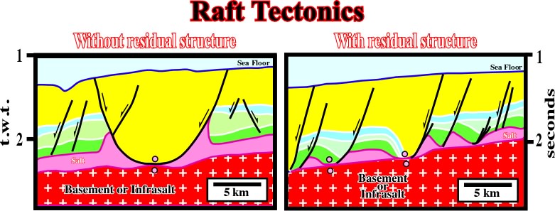
Fig. 257- On the left seismic line (zoom in fig. 258), there is no residual salt, between consecutive faults, while on the other line (zoom in fig. 259), there is a residual salt structure. Note that in this kind of halokinesis, where sliding displacement. |
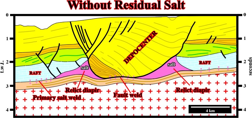
Fig. 258- The bottom of the depocenter (see fig. 257) is composed by sandstones, while the upper part (in yellow) in mainly formed by shales. No residual salt is recognized within the depocenter.The depocenter lies between two Lower-Middle Cretaceous rafts. A fault weld as well as primary salt welds underline the bottom of the evaporitic layer. Below the tectonic disharmony associated with the bottom of the evaporitic layer the infrasalt sediments are undeformed. The slightly undulations are pull-ups induced by the salt. |
|
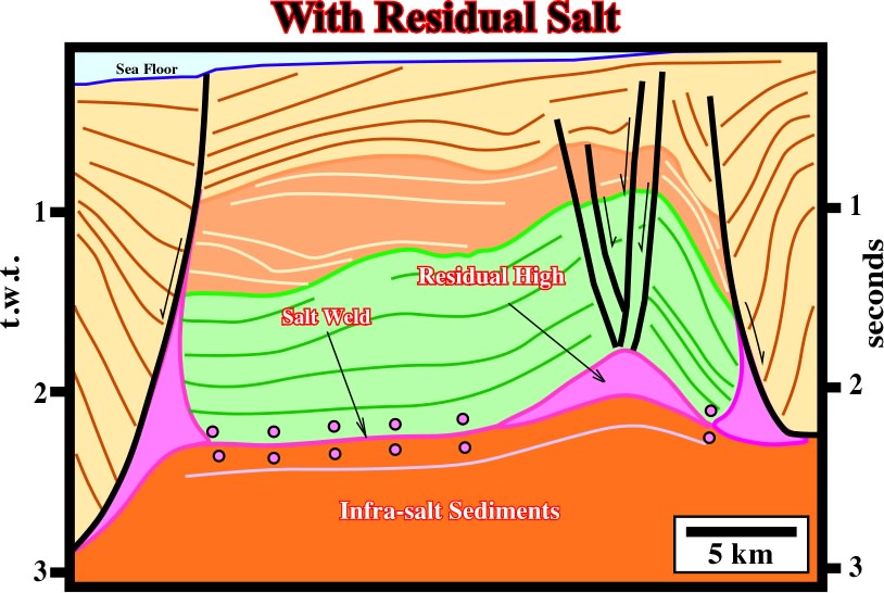
Fig. 259- On this line (see fig, 257), a residual salt structure ( raft) is evident below the Tertiary depocenter. The tectonic disharmony associated with the bottom of the evaporitic layer, characterized by sat and fault welds, is quite evident. The overlying sediments are deformed (lengthened), while the underlying are undeformed. Notice how the dip of the fault planes changes with the lithology. |
Fig. 260- A salt mound is easily recognized on this seismic line of deep Mediterranean Sea. Notice the pull-up induced by the lateral variation of the salt. |
Fig. 261- In this interpretation of a North Sea seismic line, salt diapirs are evident. They seem to be localized in particular areas of the substratum in association with major faults. However, the age of the faulting in not very clear. In our opinion, the faulting is not pre-salt, but post-salt and roughly equivalent to the age of the brown depocenter. In other words, in the Cretaceous time, the basement (paleozoic) and the cover were lengthened by a regional tectonic regime and so preexistent fault of the basement were reactivated. |
|
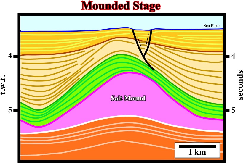
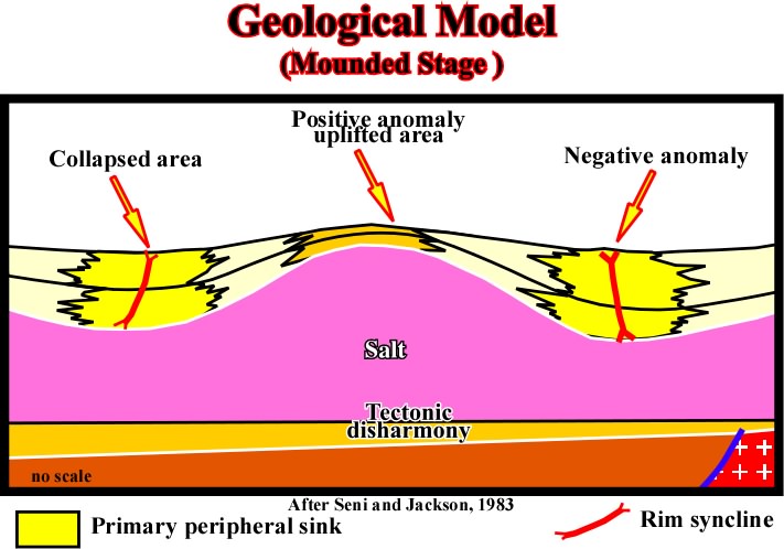
Fig.262- In this stage, notice the amplitude of the rim synclines, limiting the salt walls, and the overhang. See how the thickening of the synkinematic layers is in opposite direction. The tectonic disharmony and the pull-up induced by the salt are quite evident. |
Fig. 263- In a mounded stage the potential sandy reservoir will be deposited in the areas with maximum compensatory subsidence, i.e. in the troughs. |
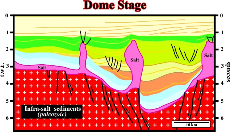
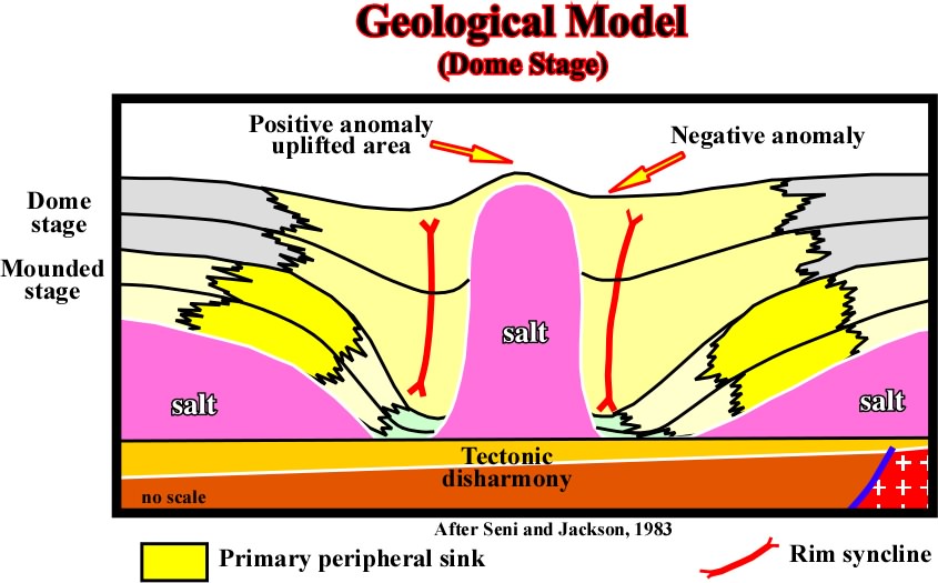
Fig. 264- The upward salt flowage induces a strong compensatory subsidence, which creates large rim synclines limiting the salt. A migration of the depocenters toward the walls of the diapir is evident. However, as said previously, a vertical geometry of the wall of a salt structure is an unstable geometry. It has a tendency to evolve in a post-dome fracturation. |
|
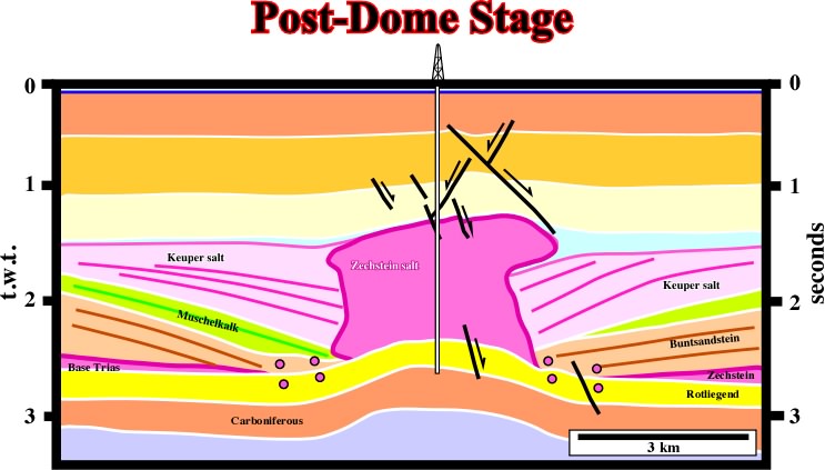
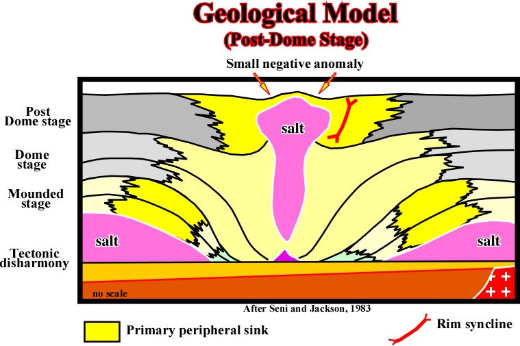
Fig. 265- Notice the displacement of the depocenters toward the wall of the post-dome structure. Generally at that stage the salt bulk is disconnected not only of the mother source layer but from the stem as well. |
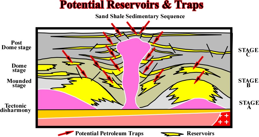
Fig. 266- The potential reservoirs are located in the deep part of the depocenters, where thickness, sandstone pinchouts or stratigraphic traps. |
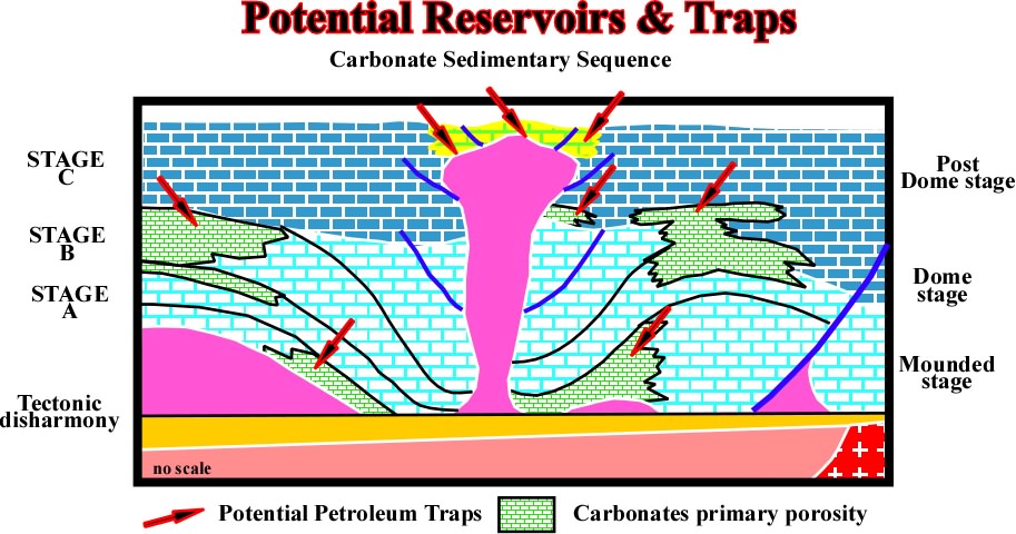
Fig. 267- Contrariwise to the sand-shale intervals, in carbonate sequences, as illustrate above, the ppotential reservoirs are located mainly in the old structural high points where the environment energy favours the development of porous carbonates. The more likely potential traps are associated with changes in facies and morphologic trpas either by juxtaposition or stratigraphic. |
|
Fig. 269- Salt domes with vertical wall are mecdhanically instable. Indeed, as the densiti of the salt is constant in depth, there is always an inversion point. Above it the preesure of the salt against the sediments is higher than the pressure of the sediments against the salt. So, the salt flows laterally. Contrariwise, below the inversionpoint, the pressure of the sediments against the salt is much higher than the pressure of the salt against the the sediments, subsequently the salt flows upward. In other words, the majority, if not all bibliographic examples of vertical salt domes, as those here illustrated, are probably far from the reality. |
Contents:
5.2- Basement not Involved
5.2.1- Evaporitic mobile substratum
5.2.1.1- Compressive dķcollement structures
5.2.1.2- Extensive salt structures
5.2.1.2.a- Basic Principles in Salt Tectonics
5.2.1.2.b- Origin of a dome
5.2.1.2.c- Evolution of dome''s flanks
5.2.1.2.d- Faults associated with domes
A) Stretch faults
B) Growth faults
5.2.1.2.e- Evolution domes and residual structures
(i) Structural changes in the salt
A. Mature domes
B. Bottom pinchoff
C. Overhang
(ii) Structural changes in sediments
a) Collapses
b) Turtle structures
c) Haggis structures
d) Raft Tectonics
5.2.1.2.f- Review of salt dome growth
A) Mounded Stage
B) Dome Stage
C) Post-dome Stage
5.2.1.2.g- Potential reservoirs and traps
5.2.1.2.h- Post-sedimentary halokinetic movements