 | Faults |
|
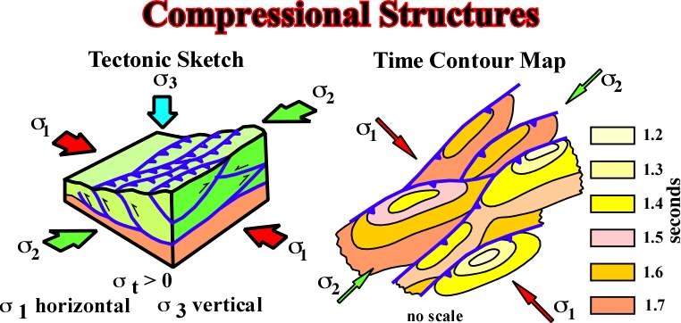
Fig. 270- Above the detachment plane (top of the mobile substratum), the compressional structures follow the conventional tectonic rulers. When 3 is vertical, anticlines and reverse fault strike parallel to 2. Generally, the reverse faults are in relay forming a typical pattern as illustrated in the sketch |
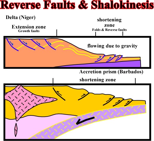
Fig. 272- Reverse faults in association with local or regional tectonic regimes are well know in deep offshore Nigeria and in accretionary prisms of convergent margins as for instance in deep offshore Barbados. |
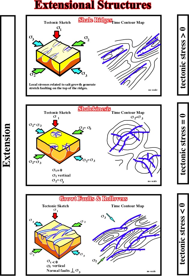
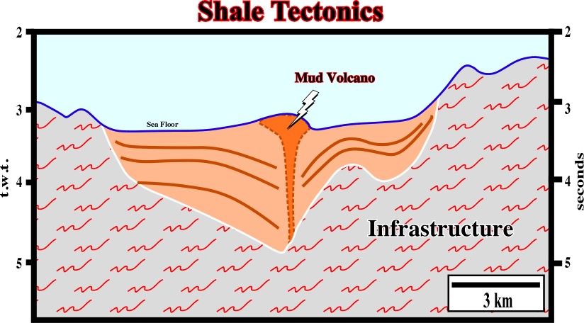
Fig. 273- Besides the local en equilibrium tectonic regime, created on the top of shale diapir, that is to say in absence of a tectonic stress, the extensional structures associated with mobile shaly substratum are mainly composed by normal faults (lengthening) striking parallel to 2. |
|
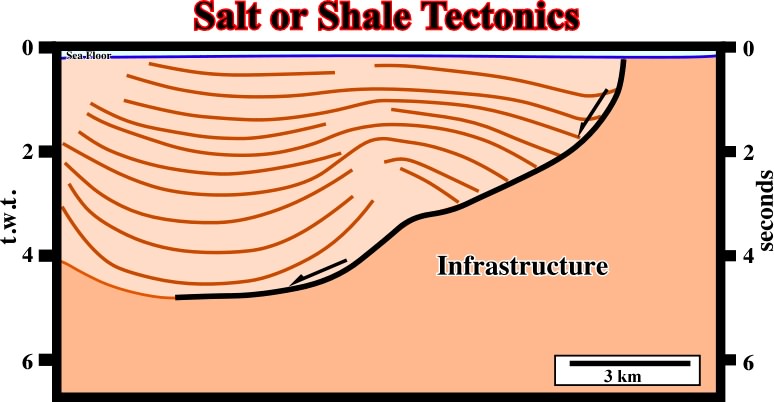
Fig. 274- Without regional context and in isolation, very often it is quite difficult to decide if a detachment plane is associated with a salt or shale interval. This is particularly true when the bottom of the mobile substratum is not well individualized. This seismic line shows a typical association between shale and salt movements. |
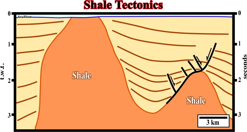
Fig. 275- On deep water of several divergent continental margins and Mediterranean basins shale tectonic, with its characteristics growth faults, mounds and diapirs, are paramount |
Fig. 276- Two well-known areas, the Niger delta and the Gulf of Mexico, can be considered as typical shale tectonic areas. On this line from Niger delta, shale diapirs are more than evident. |
|
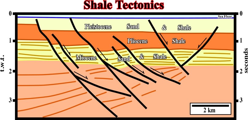
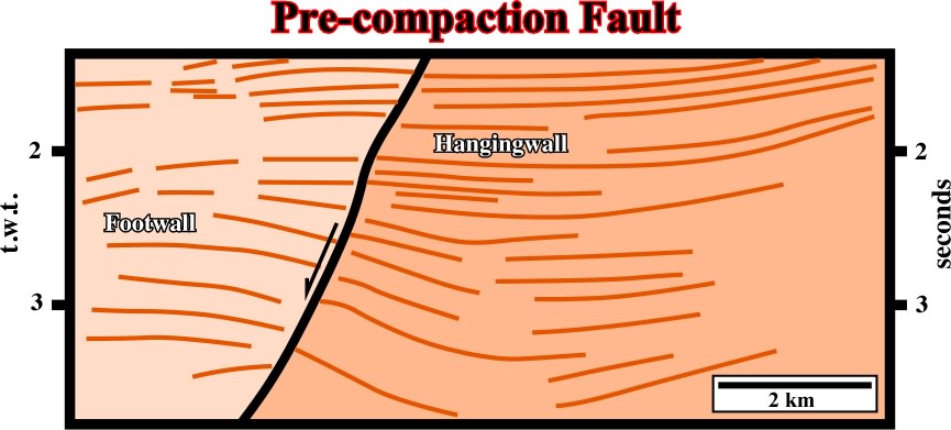
Fig. 277- On this seismic line, it is easily to recognize that the majority of the faults are pre-compaction. Indeed, the dip of those fault planes chances with the compactability of the intervals. i.e., plus compactable is the sedimentary interval lower is the dip of the fault plane. |
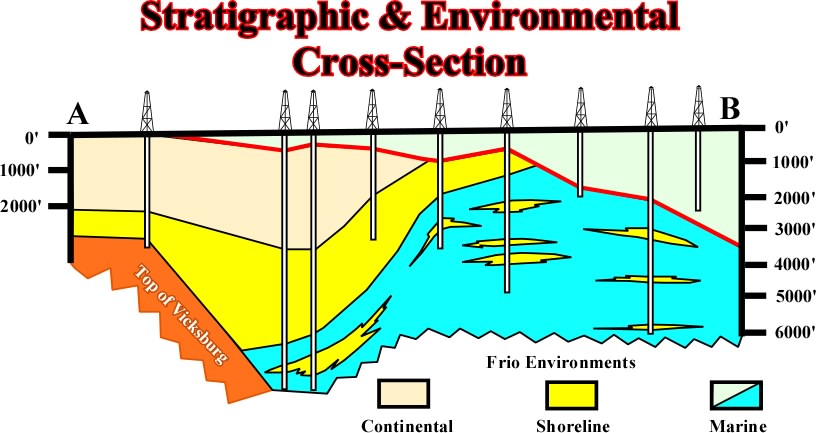
Fig. 288- This cross-section (onshore of Texas) through Agua Dulce #1, Indian Point #1, Corpus Christs ORPUS #1, Laguna Larga #1, Chevron #1, Sprint and S. Sprint #1, Carril #1, Superior #1, and Shell wells, shows: (i) the Anahuac transgression, (ii) the seaward displacement of the sedimentary environments: continental, shoreline, marine, particularly that of the Frio formation, (iii) the same upward displacement of the sedimentary environments is visible in the wells. In the same way, the electrical log of Indian Point field, illustrated on fig. 289, is very illustrative. |
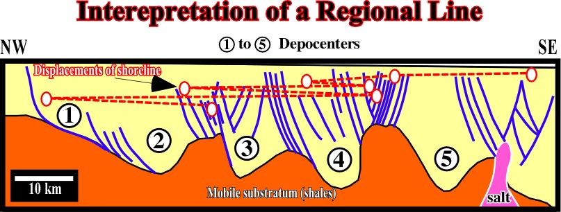
Fig. 290- On this interpretation (seismic line seaward of the cross-section illustrated on fig. 288, onshore Texas, one can recognize: (i) the displacements of the shorelines creating a regional regression, (ii) small transgressions intercalated during in the regional regression, (iii) outbuilding and upbuilding of geometry of the sedimentary intervals suggested by the different positions of the depositional coastal break (roughly the coastline during regressive episodes). |
|
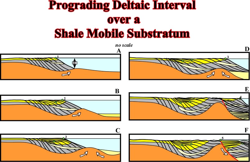
Fig. 291- The different steps, or stages, recognized on seismic lines when a deltaic interval progrades over a mobil substratum are depicted in this sketch (see text). |
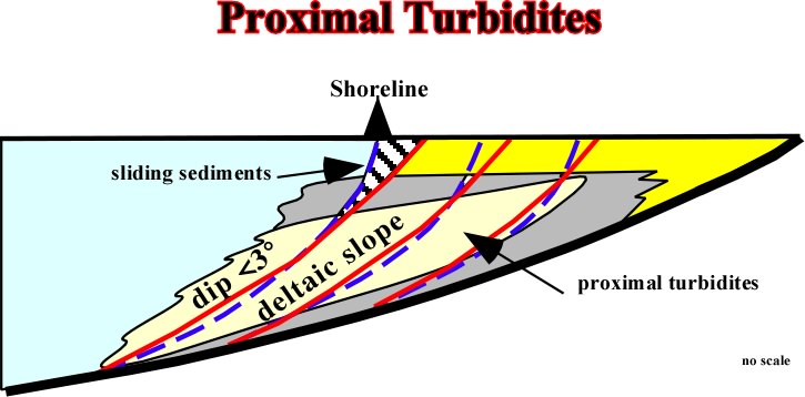
Fig. 293- When the deltaic slope is higher than 3� (the stability of a slope depends of the water depth), the delta front sandstones can glide seaward deposition in the toe of the deltaic slope (which in particular cases can correspond to the continental slope) what petroleum geologist (particular Shell''s geologist) call proximal turbidites. Admittedly, such a deposition decreases the angle of slope what eventually can allow again s seaward progradation of the delta. |
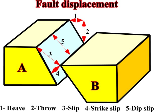
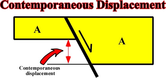
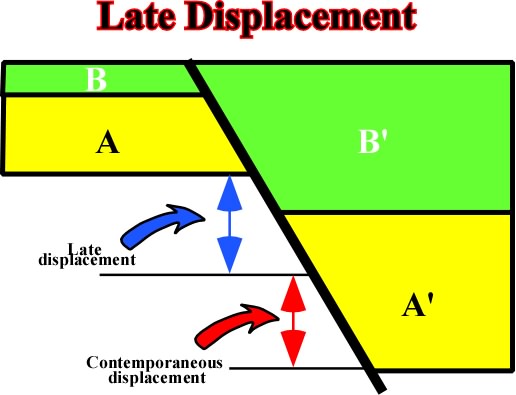
Fig. 293- Different ways geologists have to evaluated normal fault displacement. |
|
Fig. 294- Here, it is quite evident that the total displacement corresponds to the contemporaneous displacement, i.e. the expanded stratigraphic section |
Fig. 295- Here the total displacement is the sum of the contemporaneous displacement (difference between A and A'') plus the late displacement (in relation to A-A'' movement), i.e. the thickness different between B an B". |
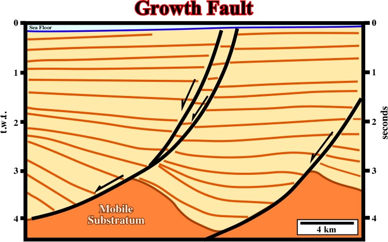
Fig. 296- When a fault is active during deposition, it means that the downthrown block, rotates, and the fault plane becomes less and less steep with depth, due to a volume problem. |
|
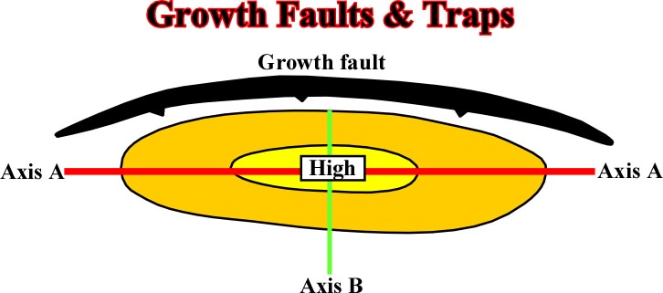
Fig. 297- In a growth fault there are two different closures: (i) parallel to the fault strike (Axis A) and (ii) perpendicular to the fault strike (Axis B). |
Fig. 297- The dip of a pre-compaction fault changes with the lithology. Higher is the dip of the fault less compactable is the juxtaposed sedimentary interval on the footwall (upthrown block). |
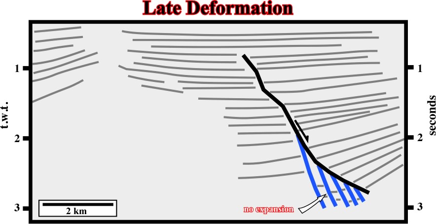
Fig. 298- On this line, the fault in red is precompaction as suggested by the changes in the dip of the fault with the lithology. On contrary, the faults in blue are posterior. They do not correspond to really normal extensional faults, but to plane discontinuities between rotated blocks (splintering or "horsetail" of the fault). |
|
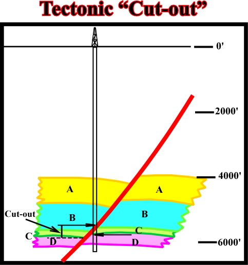
Fig. 299- As depicted, it is impossible with the well results to determine the cut-out. However, a combination of seismic and subsurface data can correctly approach the intercal not recognized in the normal faults. |
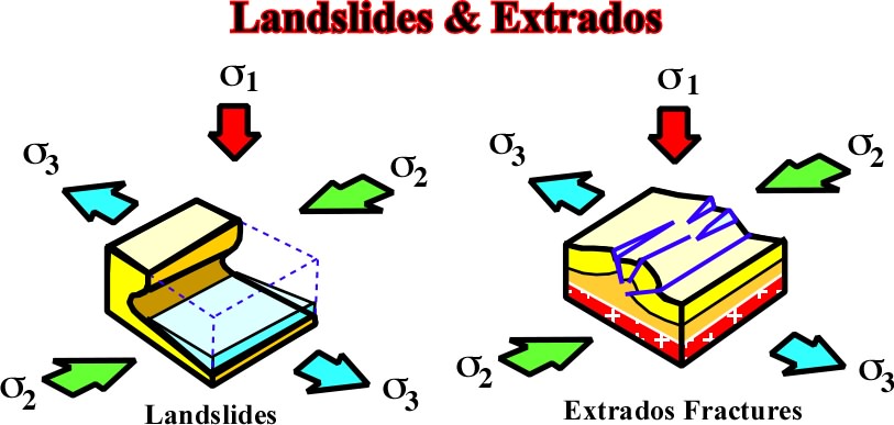
Fig. 300- Extrados fractures should not be confounded with normal faults associated with anticlines. Indeed, they with a single bed and above the neutral surface, i.e. the area extended. Normal faults affect several beds and are not contemporaneous of compressional structures |
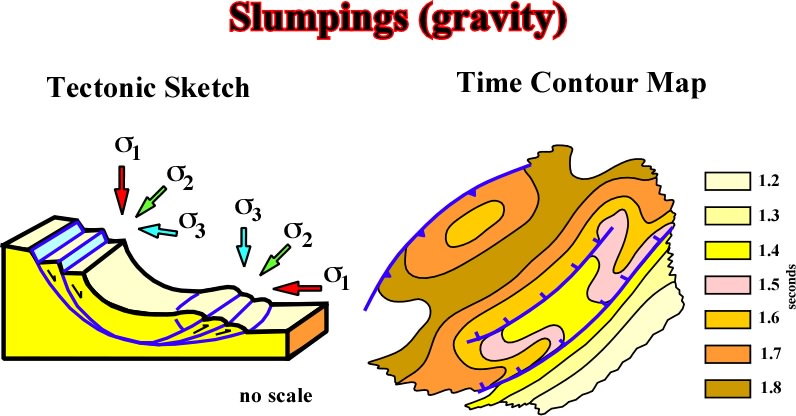
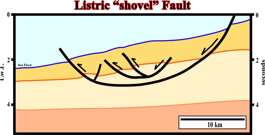
Fig. 301- These faults, which are normal updip and reverse downdip, have been labeled listric (Selley), term coming from the Greek listron, which means shovels. Indeed, in the toe of a slumping, there is development of a local compressional tectonic regime responsible by the shortening of the sediments to be accommodate to the new volume conditions (see fig. 302). |
|
Fig. 302- The sedimentary gliding, probably due to a slope instability, created a curvilinear fault plane with a normal geometry (extension updip) and a reverse geometry (compression) downdip. This kind of faulting develops in areas where the confinement pressure is relatively small, i.e. and near the surface. |
Contents:
5.2- Basement not involved (cont.)
5.2.2- Shaly mobile substratum
A) Compressional structures
B) Extensional structures
B.1- Plasticity
B.2- Undercompaction
B.3- Fault displacement
B. 4- Fault associated with shale tectonics
B.5- Growth fault displacements
B. 6- Growth faults and traps
5.3- Surface Phenomena
5.3.1- Landslide and Extrados Fractures
5.3.2- Folds and Faults associated with Gravity
